16
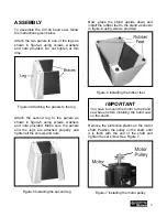
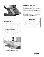
Figure-23 Loosening the guide bearings
screws
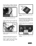
Use a screw driver and adjust the bearings
so that the space between the bearing and
the blade should be 0.02” which is
thickness of a sheet of paper. See figure-
24.
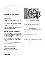
Figure-24 Distance between the guide
bearings and the blade
Now, retighten the set screws to lock the
guide bearings in place.
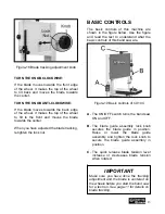
Loosen the thumb screws shown in figure-
25 and move the bearing shafts in or out so
that the guide bearings are 1/32” and the
thrust bearing is 1/64” behind the blade.
Once the bearings are at the correct
position, tighten the thumb screws to lock
the bearings in place.
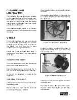
Figure-25 Support bearings adjustment
TO ADJUST THE LOWER SUPPORT
BEARINGS:
Loosen and remove the two table knobs
located under the table and uninstall the
table.
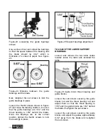
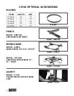
Figure-26 Guide block thrust bearing and
guide blocks
Loosen the set screws securing the guide
blocks rod and the thrust bearing rod and
adjust them so that the thrust bearing is
1/64” and the guide blocks are 1/32” behind
the blade. Re-tighten the set screws.
Loosen the set screws securing the guide
blocks and adjust the guides approximately
0.02” away from the blade and re-tighten
the set screws.

