background image


25


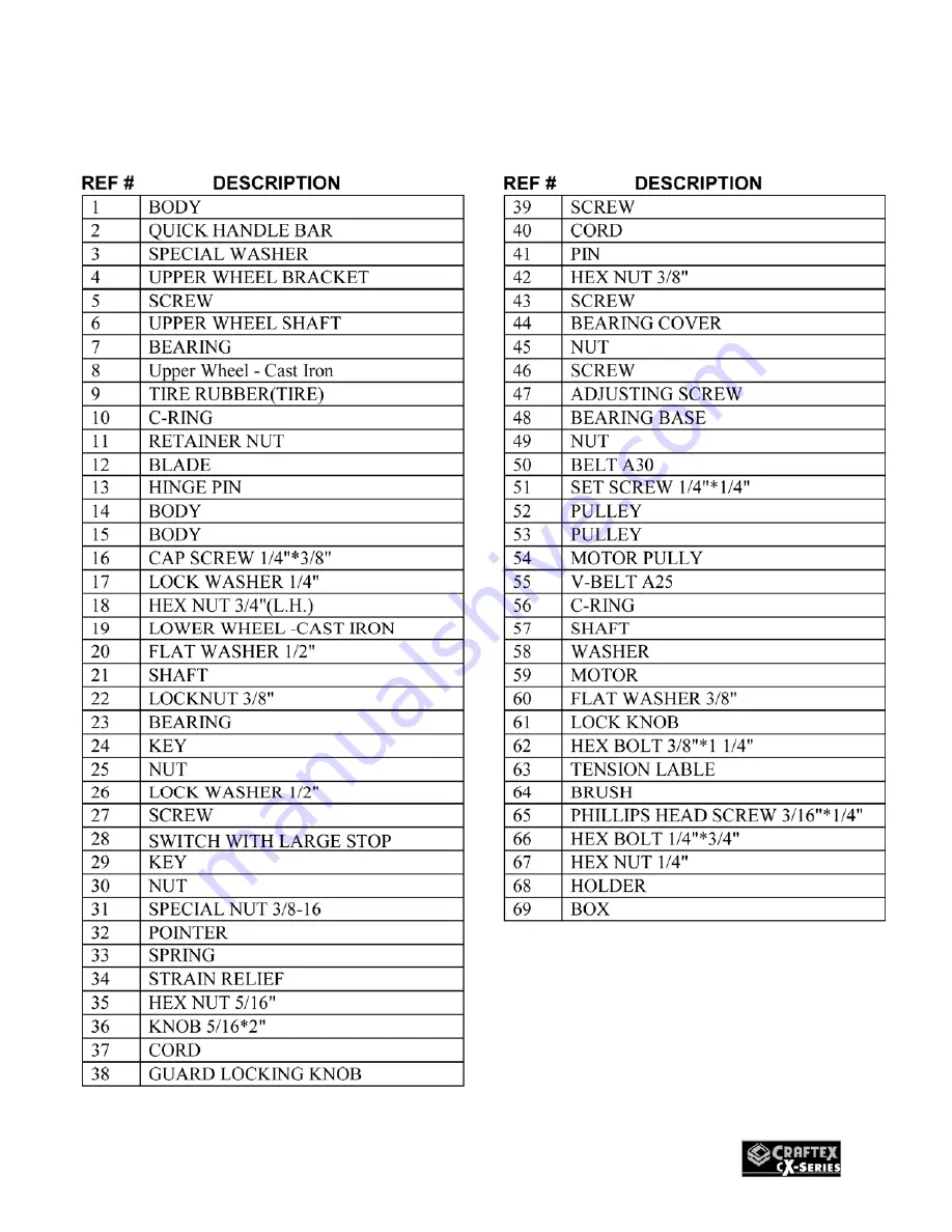
CX119N BODY PARTS LIST


Summary of Contents for CX119N

Page 1: ...CX119N 14 WOOD BAND SAW USER MANUAL Version 0 1 ...

Page 2: ...ble Stop Adjustment 14 Table Tilt Scale Calibration 15 Table Alignment 15 Guide Post 16 Speed Change Settings 16 Work Piece Inspection 17 Cast Iron Wheels 18 Coplanar Adjustment 18 Operations 19 Ripping 19 Cross Cutting 19 Re Sawing 19 Cutting Curves 19 Connecting to a Dust Collector 20 Maintenance 21 Replacing the Blade 21 Replacing the Blade Guides 21 Tilting the Table Backwards 22 Table and Bas...

Page 3: ... ENVIRONMENT is important Keep the area free of dust dirt and other debris in the immediate vicinity of your machine BE ALERT DO NOT use prescription or other drugs that may affect your ability or judgment to safely use your machine DISCONNECT the power source when changing blade and or making adjustments NEVER leave a tool unattended while it is in operation NEVER reach over the table when the to...

Page 4: ...g any adjustments the switch is in the OFF position and the cord is un plugged from the power source NEVER LEAVE the band saw unattended while it is running DO NOT attempt to remove jammed pieces unless the band saw has come to a complete stop and the power switch has been turned to the OFF position NEVER TURN ON the band saw if the blade is in contact with your stock ALWAYS ENSURE that the guide ...

Page 5: ...ed 110V 60 Hz Single Phase Amps 12 8 Amp 6 2 Amps Blade Speed 1430 2300 3250 FPM Table Size 16 x 20 Precision Cast Iron Table Tilt 10 Left and 45 Right Wheel Size 14 Maximum Blade Width 3 4 Minimum Blade Width 1 8 Floor to Table Height 38 Cutting Capacity Throat 13 5 8 Maximum Width of Cut 13 5 8 Maximum Depth of Cut 13 Ideal for Ripping Dust Collection Ports 2 Ports 4 Base Dimensions 15 x 25 Blad...

Page 6: ...djustment Handle Upper Cabinet Lock Knob Blade Guard Adjustment Hand Wheel Blade Guard Lock Blade Guard Miter Gauge Fence Rail Lower Cabinet Lock Knob Base Table Fence Magnetic Switch Powder Coated Paint Fence Cam Lock Handle Dust Ports ...

Page 7: ... ensure that nothing has been damaged during transit Open the crate and check that the machine is in good condition The hardware screws washers etc might be shipped in a plastic bag After the machine has been un packed check that all loose parts and hardware are present LIST OF CONTENTS A Table 1 B Table Insert 1 C Table Lock Knobs 2 D Table Tilt Lock Knob 1 E Table Pin 1 F Miter Gauge Holder 1 G ...

Page 8: ...s to fit a 3 prong grounded receptacle as shown in figure 1 Do not remove the grounding prong to fit it into a 2 pronged outlet Figure 1 110 volt outlet for CX119N It is strongly recommended not to use extension cords with your CX119N Always try to position your machine close to the power source so that you do not need to use extension cords If it is necessary to use an extension cord make sure th...

Page 9: ...he blade guiding through the table slot See figure 3 Figure 3 Assembling the fence Position the table on the base in such a way that the bolts under the table extend through the holes on the base Thread the two knobs on the bolts do not tighten See figure 4 Figure 4 Knobs threaded on the bolts Position the table on the table stop and the base so that the table is perpendicular to the blade See pag...

Page 10: ...ng table insert and table pin Take the fence rail and attach it to the table using cap screws provided See figure 8 Figure 8 Fence rail installed Now take the fence and pull its handle up in the unlocked position Place the fence on the fence rail and slide it towards the blade Figure 9 Installing the fence Attach the miter gauge holder and the fence holder to the back of the saw using screws and w...

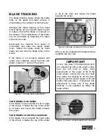
Page 11: ... KNOBS CLOCKWISE If the blade moves towards the front edge of the wheel It makes the top of the wheel to tilt back and moves the blade towards the center TURN KNOBS COUNTER CLOCKWISE If the blade moves towards the back edge of the wheel It makes the top of the wheel to tilt to the front and moves the blade towards the center Figure 12 Blade centered on the wheel When you have adjusted the blade tr...

Page 12: ...l noise coming from the machine or the machine vibrates strangely stop the machine immediately and disconnect from the power source and investigate if you can find out the problem with your machine WARNING This machine can perform many types of operations which are beyond the scope of this manual and are very dangerous if performed incorrectly The safety instructions given in this manual can not b...

Page 13: ...hows the ideal blade tension adjustment according to the width of the blade Figure 15 Quick release blade tension handle and scale ADJUSTING BLADE TENSION To adjust the blade tension lift the blade tension handle shown in figure 15 and turn it Turning the handle clockwise will tighten the tension on the blade while turning the handle counter clockwise will loosen the blade tension SUPPORT BEARINGS...

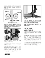
Page 14: ...teeth and the thrust bearing upper bearing 1 64 Figure 18 Distance of the bearings behind the blade Once the bearings are at the correct position behind the blade tighten the thumb screws to lock the bearings in place Adjust the lower support bearings in the same manner TABLE STOP ADJUSTMENT CX119N features a table stop which allows the table to easily come to a 90 if the table is tilted To adjust...

Page 15: ... cuts with your band saw the table should be aligned properly with the blade TO ALIGN THE TABLE Make sure the blade tension and tracking is done correctly Disconnect the machine from the power source and loosen the two knobs under the table Place a straightedge on the table so that the straightedge touches the blade and is parallel to it as shown in figure 21 Make sure the straightedge touches onl...

Page 16: ...D CHANGE SETTINGS CX119N features 3 speed settings 1430 FPM 2300FPM and 3250FPM The band saw features a motor pulley and an idler pulley The motor pulley is a 3 step pulley while the idler pulley is a 4 step pulley The first 3 steps on the idler pulley are to line up with the motor pulley for 3 feed speeds and the 4th one is to drive the pulley behind the wheel Figure 23 Pulleys wheel and drive be...

Page 17: ...bjects and it comes in contact with the blade the object might fly and hit the operator or seriously damage the blade For a safe cutting method always inspect your work piece carefully before cut and wear eye protection Some woods with excessive twisting or wrapping are un stable while cutting and are dangerous to cut because during operation the work piece can move un expectedly which either dama...

Page 18: ...re power accuracy and less wandering This will be noticed most when it comes to re sawing and making straight cuts with blades larger than 1 4 COPLANAR ADJUSTMENT Figure 26 and figure 27 show the shim for adjusting the top wheel To move the wheel out remove the nut and shims then remove the wheel Now you can add shims to the back of the wheels as required Replace the wheel and any remaining shims ...

Page 19: ...int is aligned with the blade and hold the work piece against the miter gauge Turn the band saw ON and feed the work piece against the blade RESAWING Cutting a work piece into two or more thinner pieces is called resawing Wider blades give better result when resawing To resaw a work piece make sure that the table is at a 90 with the blade and using a wider blade will give better results Adjust the...

Page 20: ...o a dust collector use a proper sized hose and make sure all the connections are sealed tightly Figure 28 CX119N connected to dust collector WARNING The saw dust produced by the band saw can go into your lungs and cause serious health problems Make sure the band saw is connected to a dust collection system while operating it ...

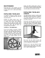
Page 21: ...l it over the wheels Once the blade is in the proper position turn the tension lever Figure 29 Replacing the blade Adjust the blade tracking See page 11 and adjust the guide bearings See page 13 Close the top and bottom cabinets and insert the table pin and table insert back REPLACING THE BLADE GUIDES The blade guides should be checked and adjusted every time the blade is replaced The blade guides...

Page 22: ...e the table and apply a few drops of oil on the trunnions BLADE TABLE ALIGNMENTS The blade and table alignments should often be checked and make sure the blade is at a 90 with the table V BELT The V belts stretch with use and should be re tensioned periodically To ensure optimum power transfer from the motor to the blade the belt must be in good condition and under proper tension Check the V belt ...

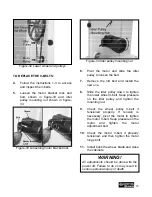
Page 23: ...d install the new one 8 Slide the idler pulley down to tighten the lower wheel V belt Keep pressure on the idler pulley and tighten the mounting nut 9 Check the wheel pulley V belt if tensioned properly If tension is necessary pivot the motor to tighten the motor V belt Keep pressure on the motor and tighten the motor adjustment bolt 10 Check the motor V belt if properly tensioned and then tighten...

Page 24: ...24 CX119N BODY PARTS BREAKDOWN ...

Page 25: ...25 CX119N BODY PARTS LIST ...

Page 26: ...26 CX119N TABLE PARTS BREAKDOWN ...

Page 27: ...27 CX119N TABLE PARTS LIST ...

Page 28: ...28 CX119N BODY PARTS BREAKDOWN LIST ...

Page 29: ...er handy All returned merchandise will be subject to a minimum charge of 15 for re stocking and handling with the following qualifications Returns must be pre authorized by us in writing We do not accept collect shipments Items returned for warranty purposes must be insured and shipped pre paid to the nearest warehouse Returns must be accompanied with a copy of your original invoice as proof of pu...

Reviews: