background image


MODEL CX208 

10” CABINET TABLE SAW 

WITH 30" FENCE 

USER MANUAL 

Version 1.0 

Summary of Contents for CX208

Page 1: ...MODEL CX208 10 CABINET TABLE SAW WITH 30 FENCE USER MANUAL Version 1 0 ...

Page 2: ...ce Rails 10 Fence 10 Magnetic ON OFF Switch 10 Installing the Saw Blade 12 Fence Scale 12 Installing Blade Guard 13 Connecting to a Dust Collector 13 Test Run 14 Blade Guard 14 ADJUSTMENTS Riving Knife 15 Work piece Inspection 15 Main Table to Blade Parallelism 16 Blade Guard Spreader and Riving Knife Alignment 16 Tensioning the V Belt 17 Replacing the V Belt 18 Maintenance 18 Parts Breakdown List...

Page 3: ...BE ALERT DO NOT use prescription or other drugs that may affect your ability or judgment to safely use your machine DISCONNECT the power source when changing drill bits hollow chisels router bits shaper heads blades knives or making other adjustments or repairs NEVER leave a tool unattended while it is in operation NEVER reach over the table when the tool is in operation ALWAYS keep blades knives ...

Page 4: ... and the power switch has been turned to the OFF position and cord is unplugged NEVER attempt to cut stock freehand always use the rip fence or miter gauge ALWAYS make sure that the rip fence is properly squared to the saw blade to prevent kickback ALWAYS make sure that your saw is in a stable position Cutting heavy long stock may alter the stability of the saw In the event that this may occur the...

Page 5: ...r tools proper care and safety procedures should be adhered to Motor 2HP 220V Single Phase Blade Guard Riving Knife CSA Approved UL897 Compliant Mitre Gauge T Slot Mitre Gauge Drive System V Belt Drive Rip Fence T Type Heavy Duty Rip Fence Cam Lever w Optical Cursor Arbor Extension Included Table Size 27 x 32 with Extension Wings Arbor Tilt Left Tilting Arbor Diameter 5 8 Blade Speed 4 000 RPM Bla...

Page 6: ...INET TABLE SAW PHYSICAL FEATURES Blade Guard Fence Miter Gauge Extension Wing Magnetic Switch Blade Tilt Hand Wheel Blade Height Hand Wheel Blade Height Lock Front Fence Rail with Tube Rear Fence Rail Blade Tilt Lock ...

Page 7: ...portation When unpacking carefully inspect the crate and ensure that nothing has been damaged during transit Open the crate and check that the machine is in a good condition LIST OF CONTENTS A Table Saw 1 B Table Extensions 2 C Cabinet Door 1 D Rip Fence 1 E Front Rear Rails 2 F Blade 1 G Miter Gauge 1 H Blade Guard 1 I Push Stick 1 J Lock Knob 1 K Hand wheel 2 L Table Insert 1 M Extension Table 1...

Page 8: ... strongly recommended not to use extension cords with your CX208 Always try to position your machine close to the power source so that you do not need to use extension cords When it is necessary to use an extension cord make sure the extension cord does not exceed 50 feet in length and the cord is 12 gauge to prevent motor damage Your CX208 should be wired with a plug having 3 prongs to fit a 3 pr...

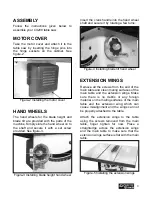
Page 9: ...into the hand wheel shaft and secure it by rotating a few turns Figure 4 Installing blade tilt hand wheel EXTENSION WINGS Remove all the screws from the end of the main table and clean mating surfaces of the main table and the extension wings Make sure there is no debris or any foreign material on the mating surfaces of the main table and the extension wing which can cause misalignment and the win...

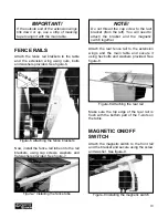
Page 10: ... hex bolts and washers provided See figure 8 Figure 8 Attaching the rear rail Make sure the top edge of the rear rail is flush with the bottom part of the T slots on the table MAGNETIC ON OFF SWITCH Attach the magnetic switch to the front rail and the bracket and secure using the screw and washer See figure 9 Figure 9 Installing the magnetic switch IMPORTANT If the outside end of the extension win...

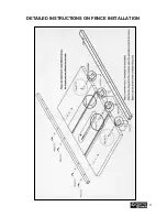
Page 11: ...11 DETAILED INSTRUCTIONS ON FENCE INSTALLATION ...

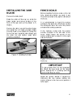
Page 12: ...e pointer window to the right or left side of the fence It is recommended to mount the pointer window to the right side of the fence so that the work piece does not cover the pointer window while cutting operation If the machine comes with the pointer window mounted to the left side of the fence simply loosen the screws on the pointer window and re install it on the right side of the fence Figure ...

Page 13: ...ece fed easily while cutting operation Figure 14 Blade guard installed CONNECTING TO A DUST COLLECTOR CX208 features a 4 diameter dust port to connect to a dust collector When connecting to a dust collector use a proper sized hose and make sure all the connections are sealed tightly It is recommended to use a proper sized dust collector with the CX208 to ensure adequate dust collection Figure 15 C...

Page 14: ... as the work piece is fed into the blade and returns to the table surface when the work piece has passed through the blade It prevents the wood chips to fly and injure the operator and it also prevents from accidental contacts of objects with the blade At the back side of the guard there is a metal plate called a spreader The spreader prevents the kerf of the work piece from pinching the blade and...

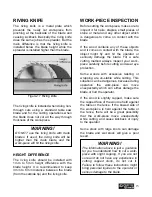
Page 15: ... object might fly and hit the operator or seriously damage the blade For a safe cutting method always inspect your work piece carefully before cutting and wear eye protection Some woods with excessive twisting or wrapping are un stable while cutting This situation can be dangerous because during operation the work piece can move unexpectedly which can either damage the blade or hurt the operator I...

Page 16: ...djusted parallel to the blade TO ADJUST THE TABLE Make sure the switch is in the OFF position and the cord is unplugged from the power source Loosen the four mounting bolts shown in figure 36 securing the table on the cabinet and adjust the table to get equal measurements on both sides of the blade Once the table is parallel to the blade retighten the mounting bolts Figure 19 Mounting bolts locati...

Page 17: ...s on the mounting block and adjust the set screws to move the spreader riving knife The set screws are to control the top side left right and bottom adjustment of the spreader riving knife Adjust the two side screws to an equal mount to move the front of the spreader riving knife left or right Now check the alignment using a straightedge as shown in figure 37 Once the spreader riving knife is in t...

Page 18: ...e the motor up to loosen the tension on the belt and remove it Install the new belt onto the pulleys and lower the motor to tension the belt When the belts are correctly tensioned tighten the hex nuts and close the motor cover MAINTENANCE 1 The unpainted components such as the precision ground cast iron table top should be protected with a coat of paste wax and then buffed dry 2 Regularly vacuum a...

Page 19: ...19 CX208 PARTS DIAGRAM ...

Page 20: ...20 ...

Page 21: ...21 ...

Page 22: ...22 ...

Page 23: ... WHEEL COVER 1 9 ROD 1 10 ANGEL LABEL 1 12 PHLP HD SCREW 3 16 24UNCX1 1 2 2 13 ON OFF SWITCH 1 14 SWITCH PLATE 1 15 SWITCH BOX 1 16 POWER WIRE 1 17 FOOT PAD 4 18 DUST COLLECT PLATE 1 19 FLANGE 1 20 BLADE 1 21 ARBOR 1 22 RUPPRT RACK 1 23 BODY 1 24 ROD 2 25 SLIDE 1 26 MOTOR 1 27 MOTOR PLATE 1 28 MOTOR PULLEY 1 CX208 PARTS LIST ...

Page 24: ...2 37 BELT 1 38 GEAR COVER 1 39 BEARING 1 40 HANDLE ASSY 1 41 SCREW BOLT 1 42 SPRING 1 43 BRACKET 2 44 SCREW 1 45 RIVING KNIFE HOLDER 1 46 FIXED BLOCK 1 47 HEX NUT 1 48 RIVING KNIFE HANDLE 1 49 NUT 1 50 HEX SCREW W WASHER 1 51 SPRING 1 52 BEARING 4 53 SCREW BUSHING 1 54 SLEEVE 1 55 SHAFT 1 56 BEARING 2 57 BEARING 1 ...

Page 25: ...NG 1 69 POSITION NUT 2 70 HEX SCREW M5XP0 8X10 1 71 FLAT WASHER 5X12X1T 3 72 MOTOR WIRE 1 73 PIN Ø5X25 2 74 CAP SCREW M8XP1 25X20 2 75 CAP SCREW M8XP1 25X35 4 76 PHILIP HD SCREW M5XP0 8X15 13 77 NUT 1 78 HEX SCREW M6XP1 0X25 2 79 STRAIN RELIEF 1 80 FLAT WASHER 6X19X2T 3 81 SET SCREW M8XP1 25X10 4 82 HEX NUT M14XP2 0 1 83 HEX SCREW M10XP1 5X20 1 84 FLAT WASHER 5 8 X40X3T 1 85 LOCKING NUT 5 8 11UNC ...

Page 26: ...EW 5 16 18UNCX3 4 4 97 FLAT WASHER 5 16 X16X2T 8 98 HEX NUT 5 16 18UNC 4 99 TENON FIXED PLATE 1 100 TENON 1 101 TENON HANDLE 1 102 SPRING 1 103 LOCKING NUT M4XP0 7 1 104 PIN Ø3X25 1 105 CAP SCREW M5XP0 8X20 2 106 SPRING WASHER Ø5 2 107 HEX SCREW M6XP1 0X40 2 108 HEX NUT M6XP1 0 2 109 BRACKET 2 110 SMALL BRACKET 1 111 HOOK 1 112 PUSH TOOL 1 113 DUST HOLE COVER 1 114 PHILIP HD SCREW M4XP0 7X12 4 115...

Page 27: ...ENCH 1 137 OPEN END WRENCH 1 138 L WRENCH 6MM 1 139 L WRENCH 4MM 1 140 L WRENCH 3MM 1 141 LABEL 1 142 LABEL 1 143 ELECTRICITY LABEL 1 A1 RIVING KNIFE 1 A2 SUPPORTING ARM 1 A3 GUARD LEFT 1 A4 GUARD RIGHT 1 A5 SEE THRU PLATE 1 A6 ANTI BACK KICK PLATE 2 A7 SPRING 1 A8 SUPPORTING PLATE 2 A9 PHILIP HD SCREW 3 16 24UNCX1 4 2 A10 LOCKING NUT 1 4 20UNC 8 A11 FLAT HD SCREW 1 4 20UNCX5 8 8 A12 FLAT WASHER 1...

Page 28: ...ATE 1 A23 PIN Ø5 30 1 A24 GUARD 1 A25 CAP SCREW M5XP0 8X12 2 A26 SUPPORTING PLATE 2 A27 WARNING LABEL 1 B1 MITER GAUGE 1 B2 GUIDE BAR 1 B3 HANDLE 1 B4 INDICATOR 1 B5 POSITION PLATE 1 B6 PAD 1 B7 FLAT WASHER 1 B8 PHILIP HD SCREW 5 32 X32UNCX5 8 3 B9 HEX NUT 5 32 3 B10 SET SCREW 1 4 20UNCX1 4 1 B11 PIN Ø3X6 1 B12 FLAT HD SCREW 1 4 X20UNCX1 4 1 B13 PIN Ø8X20MM 1 ...

Page 29: ...29 FENCE PARTS DIAGRAM ...

Page 30: ...30 FENCE PARTS LIST ...

Page 31: ...er handy All returned merchandise will be subject to a minimum charge of 15 for re stocking and handling with the following qualifications Returns must be pre authorized by us in writing We do not accept collect shipments Items returned for warranty purposes must be insured and shipped pre paid to the nearest warehouse Returns must be accompanied with a copy of your original invoice as proof of pu...

Reviews: