background image

WARNING

:  To reduce the risk of electrical shock, turn off the electricity to the fan at the main fuse box or circuit panel before you 

begin the fan installation or before servicing the fan or installing accessories.

  
1.         

READ ALL INSTRUCTIONS AND SAFETY INFORMATION CAREFULLY BEFORE INSTALLING YOUR FAN AND SAVE THESE 

INSTRUCTIONS.

  
CAUTION

:  To avoid personal injury, the use of gloves may be necessary while handling fan parts with sharp edges.

2.         Make sure all electrical connections comply with Local Codes or Ordinances, the National Electrical Code, and ANSI/NFPA 

70-1999.  If you are unfamiliar with electrical wiring or if the house/building wires are different colors than those referred to 
in the instructions, please use a qualified electrician.

3.         Make sure you have a location selected for your fan that allows clear space for the blades to rotate, and at least ten (10) feet 

(3.05 meters) of clearance between the floor and the fan blade tips.  The fan should be mounted so that the tips of the 
blades are at least thirty (30) inches (76 centimeters) from walls or other upright structures.

4.         The outlet box and ceiling support joist used must be securely mounted, and capable of supporting at least 35 pounds 

(16 kilograms).  The box must be supported directly by the building structure.  Use only CETL or CUL (Canada) or ETL or UL 
(USA) listed outlet boxes marked "FOR FAN SUPPORT." Plastic outlet boxes are not recommended. 


WARNING

:  To reduce the risk of fire, electrical shock, or personal injury, mount to the outlet box marked "Acceptable for Fan Support 

of 15.9 kg (35 lb) or less," and use the mounting screws provided with the outlet box.  Most outlet boxes commonly used for the 
support of lighting fixtures are not acceptable for fan support and may need to be replaced.  Consult a qualified electrician if in doubt.


WARNING

:  To reduce the risk of fire, electrical shock, or personal injury, wire connectors provided with this fan are designed to accept 

only one 12 gauge house wire and two lead wires from the fan.  If your house wire is larger than 12 gauge or there is more than one 
house wire to connect to the corresponding fan lead wires, consult an electrician for the proper size wire connectors to use.

  
5.         Electrical diagrams are for reference only.  
6.         After installation is complete, check that all connections are absolutely secure.
7.         After making electrical connections, spliced conductors should be turned upward and pushed carefully up into the outlet box.  

The wires should be spread apart with the grounded conductor and the equipment-grounding conductor on opposite 
sides of the outlet box.


WARNING

:  To reduce the risk of fire or electrical shock, do not use this fan with any solid state speed control device or control fan 

speed with a full range dimmer switch.  [Using a full range dimmer switch to control fan speed will cause a loud humming noise from 
fan.] 

  
8.        Do not operate the reverse switch until fan has come to a complete stop.
9.        Do not insert anything between the fan blades while they are rotating.


WARNING

:  To reduce the risk of personal injury, do not bend the blade arms during assembly or after installation.  Do not insert 

objects into the path of the blades.


WARNING

:  To avoid personal injury or damage to the fan and other items, be cautious when working around or cleaning the fan.

10.      Do not use water or detergents when cleaning the fan or fan blades.  A dry dust cloth or lightly dampened cloth will be suitable 

for most cleaning.


WARNING

:  To reduce the risk of personal injury, use 

only

 parts provided with this fan.  

The use of parts OTHER than those provided 

with this fan will void the warranty.

  
WARNING

:  

This fan MUST be installed with the safety cable provided with the fan.  Failure to use the safety cable provided may result 

in personal injury, damage to the fan or damage to other property.

CAUTION

:  Metal cover for use without light kit will be HOT if light is left on.  To reduce the risk of personal injury, light kit must be OFF.  

Do NOT use light buttons on remote or wall control if installing metal cover.

CAUTION

:  Do NOT tamper with or attempt to repair LED component of fixture.  The light source is designed for this specific 

application and should not be serviced by untrained personnel. If any servicing is required, call our customer service department.

  
11.       Light kit is d

immable to 10% with select dimmers.


Modifications not approved by the party responsible for compliance could void the user's authority to operate the equipment.  [The 
equipment refers to the remote and/or wall control and/or LED light kit.]

NOTE: This equipment has been tested and found to comply with the limits for a Class B digital device, pursuant to Part 15 of the FCC 
Rules. These limits are designed to provide reasonable protection against harmful interference in a residential installation. This 
equipment generates, uses and can radiate radio frequency energy and, if not installed and used in accordance with the instructions, 
may cause harmful interference to radio communications. However, there is no guarantee that interference will not occur in a 
particular installation. If this equipment does cause harmful interference to radio or television reception, which can be determined 
by turning the equipment off and on, the user is encouraged to try to correct the interference by one or more of the following 
measures:
 

* Reorient or relocate the receiving antenna.


* Increase the separation between the equipment and receiver.


* Connect the equipment into an outlet on a circuit different from that to which the receiver is connected.

Consult the dealer or an experienced radio/TV technician for help.

The LED light kit complies with Part 15 of the FCC Rules.  Operation is subject to the following two conditions:  (1) this LED light kit 
may not cause harmful interference, (2) this LED light kit must accept any interference received, including interference that may cause 
undesired operation.

NOTE

:  The important safety precautions and instructions appearing in the manual are not meant to cover all possible conditions and 

situations that may occur.  It must be understood that common sense and caution are necessary factors in the installation and 
operation of this fan.

SAFETY TIPS.

page 2

Summary of Contents for Bellows Duo BW250

Page 1: ...Inventory pg 3 Installation Preparation pg 4 Hanging Bracket Installation pg 4 Fan Assembly pgs 5 6 Wiring pg 7 Canopy Assembly pg 8 Final Installation pg 8 Assembly of Handheld Remote Control pg 9 Automated Learning Process Activating Code pg 10 Remote Control Operation pg 10 Testing Your Fan pg 10 Troubleshooting pg 11 Warranty pg 11 Parts Replacement pg 11 Bellows Duo page 1 APPROVED FOR USE IN...

Page 2: ...ey are rotating WARNING To reduce the risk of personal injury do not bend the blade arms during assembly or after installation Do not insert objects into the path of the blades WARNING To avoid personal injury or damage to the fan and other items be cautious when working around or cleaning the fan 10 Do not use water or detergents when cleaning the fan or fan blades A dry dust cloth or lightly dam...

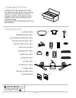
Page 3: ...ntory that all parts have been included IMPORTANT REMINDER You must use the parts provided with this fan for proper installation and safety a canopy 1 piece b hanging bracket 1 piece c downrod and hanging ball 1 piece d remote control receiver 1 piece e remote control cover 1 piece f wall control 2 pieces g canopy cover 1 piece h yoke cover 1 piece i faceplate 3 pieces j plate 1 piece k metal cove...

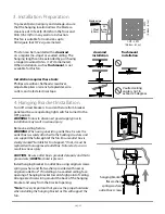
Page 4: ...n flushmount installation Turn off circuit breakers to current fixture from breaker panel and be sure operating light switch is turned to the OFF position WARNING Failure to disconnect power supply prior to installation may result in serious injury Remove existing fixture WARNING When using an existing outlet box be sure the outlet box is securely attached to the building structure and can support...

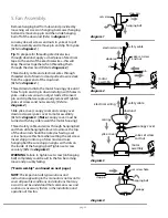
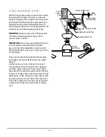
Page 5: ...ver to motor assembly Refer to diagram 3 Note Canopy cover must be turned with shiny side toward the motor housing Thread safety cable and wires through hanging ball and then slide hanging ball over downrod the top of the downrod should be noted as having a set screw hole use this hole when setting the set screw Insert stop pin into top of downrod and raise hanging ball Be sure stop pin aligns wit...

Page 6: ...old the stepladder in place and to then help lift the fan up to you once you are set on the ladder Find a secure attachment point wood ceiling joist highly recommended and secure safety cable It will be necessary to use a heavy duty wood screw washer and lock washer not supplied with the safety cable loop If necessary adjust the loop at the end of the safety cable The loop at the end of the safety...

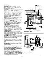
Page 7: ...not wish to use the wall control please proceed to Section 7 to continue with fan installation To install wall control remove existing wall switch Wire one of the wall controls with wire connectors provided as shown in diagram at right Wrap each wire connector separately with electrical tape as an extra safety measure Gently push wires and taped wire connectors into outlet box Install one 12 volt ...

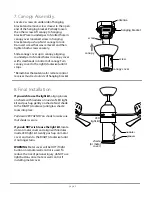
Page 8: ...r must rest outside of hanging bracket canopy cover screw canopy hanging bracket screw antenna 8 Final Installation If you wish to use the light kit align grooves on shade with nodules on inside of LED light kit and push up gently on shade Twist shade to the RIGHT clockwise until glass shade locks into place Pull down VERY GENTLY on shade to make sure that shade is secure If you do NOT wish to use...

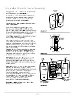
Page 9: ...OTE Make sure to align narrower ends of remote control cover before closing Squeeze top and bottom of remote control cover together until you hear a click at each end indicating that the remote control cover has closed completely IMPORTANT Store the handheld remote control away from excess heat or humidity To prevent damage to handheld remote control remove the battery if handheld remote control w...

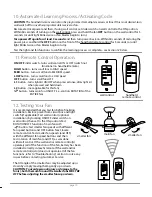
Page 10: ...tion ON OFF slider switch turns wall control ON or OFF switch not functional on handheld remote HIGH button turns small fans to HIGH speed MED button turns small fans to MEDIUM speed LOW button turns small fans to LOW speed OFF button turns small fans OFF L1 button turns light kit ON OFF when pressed once dims light kit when pressed and held down L2 button not applicable for this fan button turns ...

Page 11: ...NTY CRAFTMADE warrants this fan to the original household purchaser for indoor use under the following provisions 1 YEAR WARRANTY CRAFTMADE will replace or repair any fan which has faulty performance due to a defect in material or workmanship Contact Craftmade Customer Service at 1 800 486 4892 to arrange for return of fan Return fan shipping prepaid to Craftmade We will repair or ship you a repla...

Page 12: ...llation finale pge 8 Assemblage du module de télécommande pge 9 Processus d apprentissage automatisé Activer code pge 10 Utilisation de la télécommande pge 10 Tester votre ventilateur pge 10 Dépannage pge 11 Garantie pge 11 Remplacement des pièces pge 11 poids net du ventilateur 7 96 kg 17 5 lb IMPRIMÉ EN CHINE LISEZ ET CONSERVEZ CES INSTRUCTIONS POUR UN USAGE ULTÉRIEUR page 1 Guide d installation...

Page 13: ...et 9 Ne rien insérer entre les pales du ventilateur lorsqu elles sont en mouvement AVERTISSEMENT En vue de réduire le risque de blessures corporelles évitez de plier les bras de pales pendant le montage ou après installation Ne pas introduire d objets dans la trajectoire des pales AVERTISSEMENT Pour éviter toute blessure corporelle ou dommage au ventilateur et autres éléments faites preuve de prud...

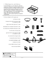
Page 14: ...e l l ensemblé du moteur 1 pièce m sacs de quincaillerie page 3 1 Déballage du ventilateur Ouvrez l emballage avec soin Retirez les articles des protections en mousse de polystyrène Retirez le boîtier du moteur et placez le sur un tapis ou de la mousse en polystyrène pour éviter d endommager son fini Ne jetez pas la boîte du ventilateur ni les protections en mousse de polystyrène au cas où le vent...

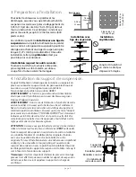
Page 15: ...riger l ouverture du support de suspension vers le point haut du plafond Disposez le câblage derrière le support de suspension de telle sorte qu il soit à l écart de l ouverture du support Remarque Il est très important d utiliser les pièces de montage prévues à cet effet lorsque vous installez le support de suspension du fait que celles ci seront appelées à supporter la charge du ventilateur page...

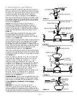
Page 16: ...chéma 2 Vissez la tige de suspension dans l étrier du l ensemble du moteur jusqu à ce que les trous pratiqués dans la tigue de suspension réservés pour la clavette et la goupille soient alignés sur les trous de l étrier veillez à ce que les fils ne soient pas torsades Réinsérez la goupille et le clip précédement retirés Serrez les vis de fixation et les écrous de l étrier fermement Voir schéma 2 G...

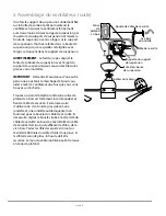
Page 17: ...de suspension avec l ergot du support de suspension peut causer des blessures graves voire mortelles IMPORTANT Demandez l assistance d une autre personne pour tenir le marcheped et pour vous aider à lever le ventilateur une fois que vous vous trouvez sur l échelle Trouvez un point d attache solide une solive de plafond en bois est fortement recommandée et fixez le câble de sécurite Il sera nécessa...

Page 18: ...pourvus de ruban isolant avec soin dans la boîte de sortie Laissez l antenne posée hors du support de suspension VEUILLEZ NOTER La commande murale et ou le module de télécommande sont nécessaires pour faire fonctionner le ventilateur Si vous ne souhaitez pas utiliser la commande murale veuillez passer à la Section 7 pour continuer avec l installation du ventilateur Pour installer la commande mural...

Page 19: ...ez vous que l antenne du récepteur de la commande à distance doit être posée hors du support de suspension couvercle de monture vis monture support de suspension vis antenne Si vous souhaitez utiliser le ventilateur avec le kit d éclairage alignez les rainures de l abat jour avec les nodules à l intérieur du kit d éclairage DEL et poussez doucement sur l abat jour Tournez l abat jour vers la DROIT...

Page 20: ...éma 3 REMARQUE Assurez vous d aligner les extrémités plus étroites du couvercle de la commande à distance avant de refermer Serrez les parties supérieure et inférieure du couvercle de la commande à distance l une contre l autre jusqu à ce que vous entendiez un déclic à chaque extrémité indiquant que le couvercle de la commande à distance est en place et verrouillé IMPORTANT Entreposez la commande ...

Page 21: ...du kit d éclairage si appuyé une fois fait varier l intensité de l éclairage lorsqu il est appuyé et maintenu enfoncé Bouton L1 not applicable for this fan Bouton Utilisé pour INVERSER le sens de rotation des pales le ventilateur doit être réglé sur la vitesse lente avant d inverser la rotation des pales 12 Tester votre ventilateur Il est recommandé de tester le ventilateur avant de mettre la dern...

Page 22: ...ue la les vis de pression de la chape du boîtier du moteur est sont bien serrée s 2 Vérifiez que la vis de pression de la boule de suspension est bien serrée GARANTIE À VIE LIMITÉE DE CRAFTMADE CRAFTMADE garantit ce ventilateur à l acheteur résidentiel original pour une utilisation à l intérieur en vertu des dispositions suivantes GARANTIE D UN AN CRAFTMADE remplacera ou réparera tout ventilateur ...

Page 23: ...ág 4 Ensamblaje del ventilador Págs 5 6 Instalación eléctrica Pág 7 Colocación de la cubierta decorativa Pág 8 Instalación final Pág 8 Ensamblaje del control remoto de mano Pág 9 Proceso de aprendizaje automático El activar el código Pág 10 Funcionamiento del control remoto Pág 10 Verificación del funcionamiento del ventilador Pág 10 Localización de fallas Pág 11 Garantía Pág 11 Piezas de repuesto...

Page 24: ...entilador 8 No utilizar el interruptor de reversa hasta que el ventilador se haya parado completamente 9 No insertar ningún objeto entre las aspas mientras estén rotando ADVERTENCIA Para reducir el riesgo de daño corporal no doblar los brazos de las aspas durante el ensamblaje ni durante la instalación No insertar objetos entre las aspas mientras estén rotando ADVERTENCIA Para reducir el riesgo de...

Page 25: ...l unidad del motor 1 unidad m paquetes de artículos de ferretería 1 Desempaquetado del ventilador Abrir el empaque cuidadosamente Sacar los artículos del embalaje Sacar el motor y ponerlo en una alfombra o en el embalaje para evitar rayar el acabado Guardar la caja de cartón o el empaquetamiento original en caso de que tenga que mandar el ventilador para alguna reparación Comprobar las piezas del ...

Page 26: ...te conectada a la estructura del edificio y que sea capaz de sostener el peso total del ventilador Asegurarse de que la caja de salida indique claramente que Sirve para ventilador FOR FAN SUPPORT si no se debe reemplazar con una caja de salida aprobada El no hacer el cambio si es necesario puede resultar en lesiones graves PRECAUCIÓN asegurarse de que la caja de salida esté conectada a tierra corr...

Page 27: ...do brillante dé al bastidor del motor Pasar los cables y el cable de seguridad por la bola que sirve para colgar y luego deslizar la bola que sirve para colgar sobre el tubo la parte de arriba del tubo debe tener el agujero para el tornillo de fijación en ese extremo usar ese agujero al colocar el tornillo de fijación Introducir el perno de tope en la parte de arriba del tubo y subir la bola que s...

Page 28: ...causar lesiones graves o la muerte Sugerencia debido al tamaño anchura del ventilador se le aconseja solicitar ayuda de otra persona para mantener la escalera sujeta y para que le suba el ventilador cuando usted ya esté preparado en la escalera para colgarlo Encontrar un punto de acoplamiento seguro se recomienda la viga de madera en el techo y asegurar el cable de seguridad Utilizar tornillo para...

Page 29: ...ilizar el control de pared favor de pasar a la sección 7 para seguir con la instalación del ventilador Para instalar el control de pared quitar el interruptor de pared existente Alambrar uno de los controles de pared con los conectores para cable provistos así como se muestra en el diagrama al lado Como una medida de seguridad adicional envolver cada conector para cable con cinta aisladora Delicad...

Page 30: ...eloj hasta que ya no gire Recordar que la antena del receptor del control remoto debe quedar fuera del soporte de montaje Si desea utilizar el juego de luz alinear las ranuras en la pantalla con los nódulos dentro del juego de luz LED y empujar la pantalla delicadamente hacia arriba Girar la pantalla hacia la DERECHA en sentido de las agujas del reloj hasta que se quede encajada Con MUCHO CUIDADO ...

Page 31: ...e al diagrama 3 NOTA asegurarse de alinear los extremos más angostos de la cubierta del control remoto antes de cerrarla Apretar la parte superior e inferior de la cubierta del control remoto hasta que se oiga un clic en cada extremo lo cual indicará que se haya cerrado completamente la cubierta del control remoto IMPORTANTE guardar el control remoto lejos del calor excesivo o la humedad Para prev...

Page 32: ...z el juego de luz no se aplica para este ventilador ENCIENDE APAGA el ventilador principal es decir controla la ROTACIÓN del ventilador ENTERO Se le recomienda poner el ventilador a prueba antes de terminar la instalación Regresar la corriente de electricidad en el cortacircuitos y el interruptor de la luz si se aplica Poner a prueba el control de pared instalación opcional localizando el interrup...

Page 33: ...arantía Piezas de repuesto Para piezas o información referirse al Inventario de piezas en la página 3 Servicio al cliente de Craftmade 1 800 486 4892 www craftmade com página 11 GARANTÍA LIMITADA DE POR VIDA DE CRAFTMADE CRAFTMADE garantiza este ventilador al comprador original de grupo familiar para uso interior con las siguientes condiciones GARANTÍA DE 1 AÑO CRAFTMADE reemplazará o reparará cua...

Reviews: