

page 9
14. Testing Your Fan.
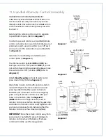
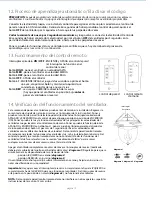
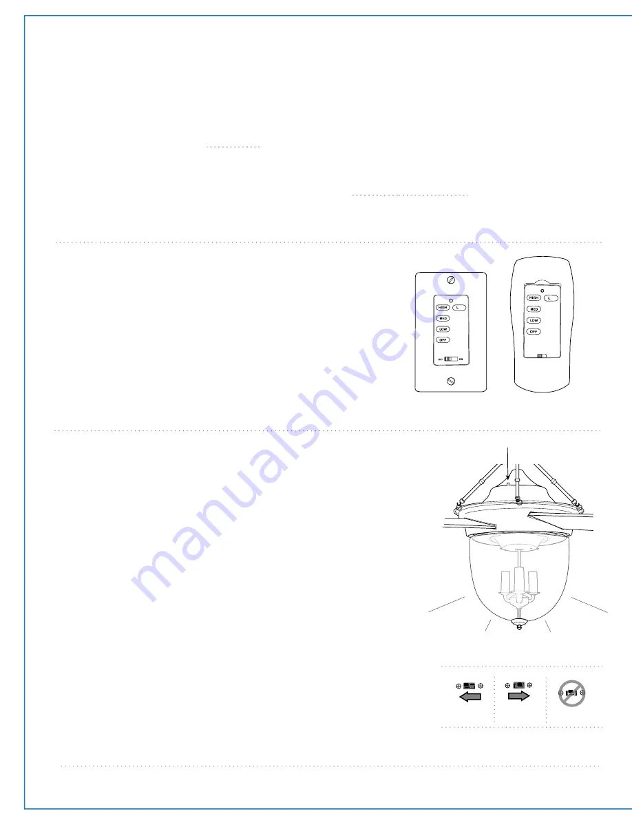
13. Remote Control Operation.
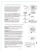
ON/OFF
slider switch - turns
wall control
ON or OFF
(switch not functional on handheld
remote)
HIGH
button - turns
fan
to HIGH speed
MED
button - turns
fan
to MEDIUM speed
LOW
button - turns
fan
to LOW speed
OFF
button - turns
fan
OFF
L1
button -
turns
light kit
ON/OFF when pressed once;
dims
light kit
when pressed and held down
REV
button - used to REVERSE blade direction
(fan must be set on
low
before
reversing blade
direction)
wall control
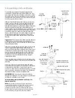
CAUTION
:
The wall and/or handheld remote control can be programmed to multiple receivers or fans. If this is not
desired, turn wall switch off to any other programmable receiver or fan.
Restore electrical power and then, if using wall control, set slider switch on wall control to the ON position. Within
60 seconds of turning on the wall control, press and hold the fan
OFF
button on the wall control for 5 seconds or
until light blinks twice.
Turn power off again for at least 5 seconds
and then turn power back on. Within 60 seconds of restoring the
power, press and hold the fan
OFF
button on the front of the handheld remote control for 5 seconds or until light
blinks twice.
Test the light and fan functions to confirm the learning process is complete--
see Section 14 below.
handheld
remote control
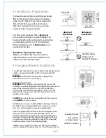
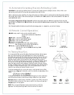
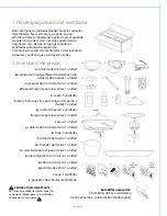
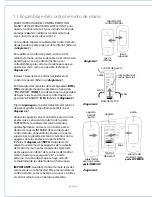
12. Automated Learning Process./Activating Code.
diagram 1
diagram 2
diagram 3
diagram 4
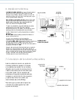
It is recommended that you test fan before finalizing installation. Restore power
from circuit box and light switch (if applicable). Test wall control (optional
installation) by locating ON/OFF slider switch on wall control, then set to the ON
position. Test light and dimmer function and then test fan speeds. Next, locate
handheld remote control. Test the light ON/OFF function by pressing the L1
button; test the dimmer function by pressing the L1 button and holding it down
for1 second. Test fan speeds with the different fan speed buttons. If the wall
and/or handheld remote control operates all of the functions of the fan, battery
has been installed correctly. If the wall and/or handheld remote control do (does)
not operate all of the fan/light functions, refer to "Troubleshooting" section to
solve any issues before contacting Customer Service.
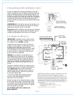
Turn fan completely off
before
moving the reverse switch (located on top of the
motor housing). (
diagram 1
) Set reverse switch to recirculate air depending on the
season:
- LEFT position in summer (
diagram 2
)
- RIGHT position in winter (
diagram 3
)
A ceiling fan will allow you to raise your thermostat setting in summer and lower
your thermostat setting in winter without feeling a difference in your comfort.
Important
: Reverse switch must be set either
completely to the LEFT
or
completely
to the RIGHT
for fan to function. If the reverse switch is set in the
middle
position
(
diagram 4
), fan will not operate.
NOTE
: If the wall control/handheld remote control interferes with other
appliances, turn off power and go back to the instructions in Section 12.
1
1
-
1
1
-
Reverse Switch


