

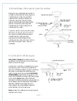

Troubleshooting.
Warranty.
Parts Replacement.
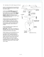
WARNING:
Failure to disconnect power supply
prior to troubleshooting any wiring issues may
result in serious injury.
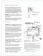
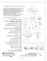
For parts and information, please refer to
"Parts Inventory" on page 2.
Craftmade/Ellington Customer Support:
1-800-486-4892
www.craftmadebrands.com
CRAFTMADE/ELLINGTON LIFETIME WARRANTY:
CRAFTMADE/ELLINGTON warrants this fan to the original
household purchaser for indoor use under the following
provisions:
1-YEAR WARRANTY: CRAFTMADE/ELLINGTON will replace
or repair any fan which has faulty performance due to a
defect in material or workmanship. Contact
Craftmade/Ellington Customer Service at
1-800-486-4892
to arrange for return of fan. Return fan, shipping prepaid, to
Craftmade/Ellington. We will repair or ship you a
replacement fan, and we will pay the return shipping cost.
5-YEAR WARRANTY: CRAFTMADE/ELLINGTON will repair or
replace at no charge to the original purchaser any fan
motor that fails to operate satisfactorily when failure
results from normal use.
RETURN FAN MOTOR ONLY, shipping prepaid, to
Craftmade/Ellington. We will repair or ship purchaser a
replacement motor and Craftmade/Ellington will pay the
return shipping cost.
6-YEAR to LIFETIME LIMITED WARRANTY:
CRAFTMADE/ELLINGTON will repair the fan, at no charge
for labor only to the original purchaser, if the fan motor
fails to operate satisfactorily when failure results from
normal use. Parts used in the repair will be billed to the
purchaser at prevailing prices at time of repair.
The purchaser shall be responsible for all costs incurred
in the removal, reinstallation and shipping of the product
for repairs.
This warranty does not apply when damage from
mechanical, physical, electrical or water abuse results in
causing the malfunction. Deterioration of finishes or other
parts due to time or exposure to salt air is specifically
exempted under this warranty.
Neither Craftmade/Ellington nor the manufacturer will
assume any liability resulting from improper installation or
use of this product. In no case shall the company be liable
for any consequential damages for breach of this, or any
other warranty expressed or implied whatsoever. This
limitation as to consequential damages shall not apply in
states where prohibited.
page 10
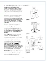
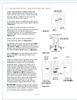
Problem:
Fan fails to operate.
Solutions:
1. Check wall switch to fan/wall control.
2. Check to be sure wall control (optional use) is wired
properly.
3. Check to be sure fan is wired properly.
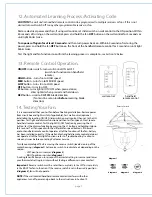
4. Learning process between fan, handheld remote control
and, if applicable, wall control may not have been successful
and code was not activated. Turn off power and repeat
instructions in Section 12 (page 10).
5. Check that red light on handheld remote control turns on
when a button is pressed indicating that the battery is good.
Problem:
Light kit not lighting.
Solutions:
1. Check wall switch to fan/wall control.
2. Check that bulb is installed correctly.
3. Check that wires in canopy are wired properly.
4. Verify that molex connections in light kit fitter are
connected properly.
5. Learning process between fan, handheld remote control
and, if applicable, wall control may not have been successful
and code was not activated. Turn off power and repeat
instructions in Section 12 (page 9).
Problem:
Fan operates but light fails.
Solutions:
1. Check that bulb is installed correctly.
2. Check that wires in canopy are wired properly.
3. Replace defective bulb with same type of bulb.
4. Verify that molex connections in light kit fitter are
connected properly.
Problem:
Fan and light fail to operate with wall control
(optional) and/or handheld remote control.
Solutions:
1. Check battery power in handheld remote control.
2. Learning process between fan, handheld remote control
and, if applicable, wall control may not have been successful
and code was not activated. Turn off power and repeat
instructions in Section 12 (page 10).
3. If using optional wall control, check that battery in wall
control is still good.
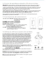
Problem:
Lighting source (up-light, down-light or both) not
functioning.
Solution:
Wattage Limiting Device has interrupted the flow of
electricity to the light source. Ensure bulbs total no more than
190W in the light source.
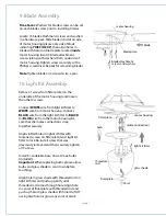
Problem:
Fan wobbles.
Solutions:
1. Use the balancing kit in one of the hardware packs.
If no
blade balancing kit is provided, please call Customer Support,
1-800-486-4892, to request one.
2. Check to be sure set screw(s) on motor housing yoke is
(are) tightened securely.
3. Check to be sure set screw on hanging ball is tightened
securely.
NOLI1412


