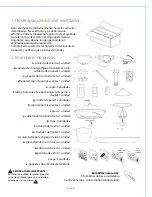
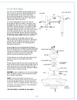
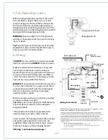
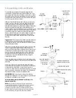
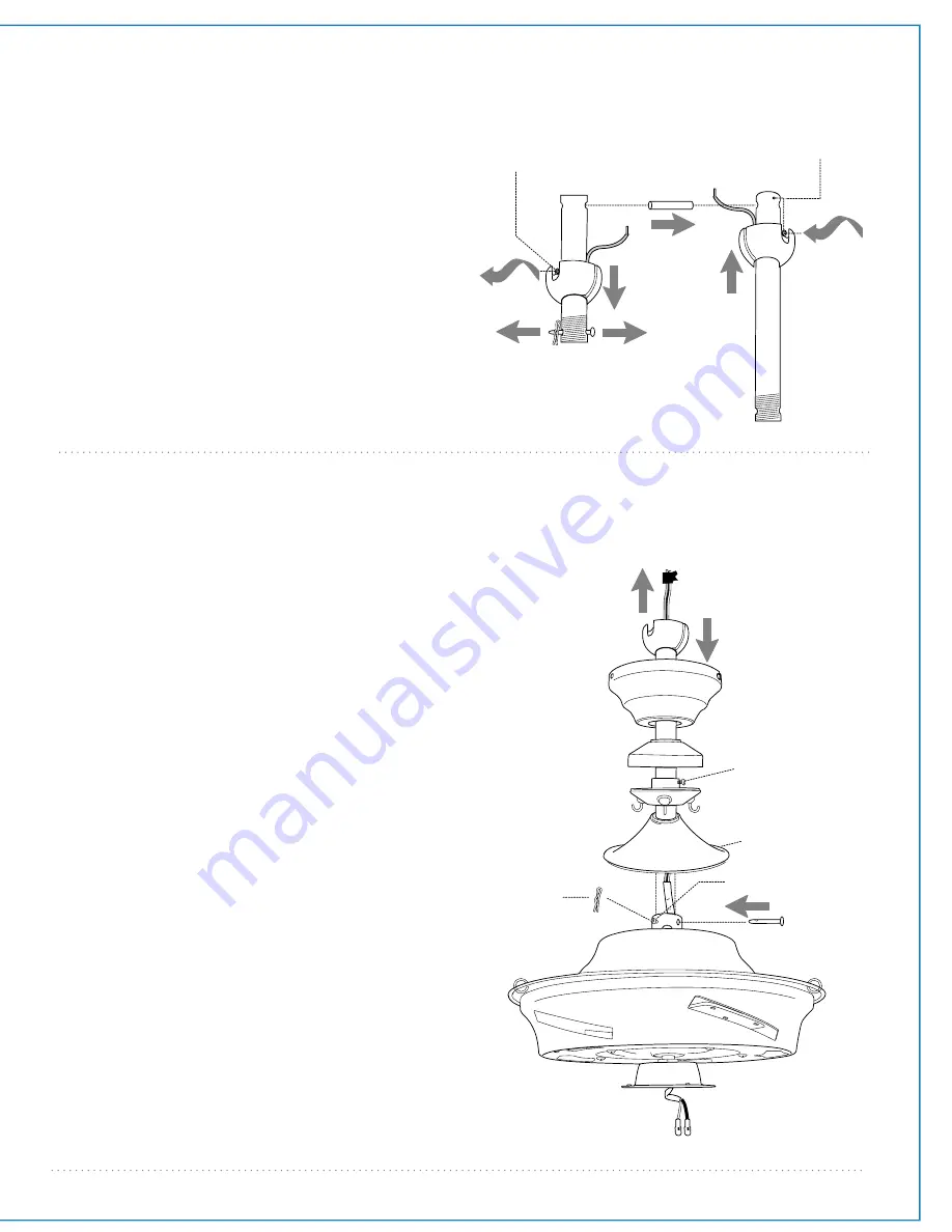
background image

page 4

motor

housing

5. Fan Assembly.

yoke set screw

downrod

rod support cap

rod support
set screw

rod support

canopy

yoke cover

electrical wiring

clip

pin

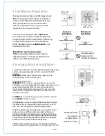
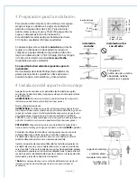
If you wish to extend the hanging length of your 
fan, you must remove the hanging ball from the 
downrod provided to use with an extended 
downrod (sold separately). [

If you wish to use the  

downrod provided, please proceed to instructions 
following the dotted line below.

]

To remove hanging ball, loosen set screw on 
hanging ball and remove the pin and clip. Lower 
hanging ball and remove stop pin. Slide hanging 
ball off the original downrod, A, and slide it down 
the longer downrod, B (the top of the downrod 
should be noted as having a set screw hole; use this 
hole when setting the set screw). Insert stop pin 
into top of extended downrod and raise hanging 
ball. Be sure stop pin aligns with slots on the inside 
of the hanging ball. Tighten set screw securely.

Tip

: To prepare for threading electrical wires 

through downrod, apply a small piece of electrical 
tape to the ends of the electrical wires--this will 
keep the wires together when threading them 
through the downrod.

Loosen yoke set screws and nut at top of motor 
housing.  Remove pin and clip from downrod (if you 
have not already done so). Slide downrod through 
canopy, rod support cap, rod support (loosen rod 
support set screw to prevent scratching the 
downrod finish) and then the yoke cover.

Thread electrical wires through downrod and pull 
extra wire slack from the upper end of the 
downrod.

Thread downrod into the motor housing yoke until 
holes for pin and clip in downrod align with holes in 
yoke--

make sure wires do not get twisted

. Re-insert 

pin and clip that were previously removed. Tighten 
yoke set screws and nut securely.

WARNING

: Failure to tighten set screw (on hanging 

ball) completely could result in the fan becoming 
loose and possibly falling. 

NOTE:

  The important safety precautions and 

instructions appearing in the manual are not meant 
to cover all possible conditions and situations that 
may occur.  It must be understood that common sense 
and caution are necessary factors in the installation 
and operation of this fan.

["Fan Assembly"  continued on next page.]

set screw hole

set screw

hanging ball

pin

A

B

pin

clip

Summary of Contents for Cavalier CAV52ABZ5LK

Page 1: ...rt Assembly pg 6 Blade Assembly pg 7 Light Kit Assembly pg 7 Handheld Remote Control Assembly pg 8 Automated Learning Process Activating Code pg 9 Remote Control Operation pg 9 Testing Your Fan pg 9 Troubleshooting pg 10 Warranty pg 10 Parts Replacement pg 10 net weight of fan 29 7 lb 13 47 kg PRINTED IN CHINA READ THESE INSTRUCTIONS AND SAVE THEM FOR FUTURE USE For Model CAV52ABZ5LK CAV52PT5LK Ca...

Page 2: ...ires consult an electrician for the proper size wire connectors to use WARNING If using this fan in a DAMP location this fan must be connected to a supply circuit that is protected by a Ground Fault Circuit Interrupter GFCI to reduce the risk of personal injury electrical shock or death 5 Electrical diagrams are for reference only Light kits that are not packed with the fan must be CETL or CUL in ...

Page 3: ...iece d rod support cap 1 piece e rod 3 pieces f downrod and hanging ball with pin and clip 1 piece g wall control 2 pieces h rod support 1 piece i plate 1 piece j remote control cover 1 piece k faceplate 3 pieces l yoke cover 1 piece m motor housing 1 piece n light kit fitter 1 piece o finial plate 1 piece p finial 1 piece q glass shade 1 piece r blade 5 pieces s hardware packs page 2 IMPORTANT RE...

Page 4: ...ker panel and be sure operating light switch is turned to the OFF position WARNING Failure to disconnect power supply prior to installation may result in serious injury Remove existing fixture WARNING When using an existing outlet box be sure the outlet box is securely attached to the building structure and can support the full weight of the fan Ensure the outlet box is clearly marked Suitable for...

Page 5: ...he ends of the electrical wires this will keep the wires together when threading them through the downrod Loosen yoke set screws and nut at top of motor housing Remove pin and clip from downrod if you have not already done so Slide downrod through canopy rod support cap rod support loosen rod support set screw to prevent scratching the downrod finish and then the yoke cover Thread electrical wires...

Page 6: ...he fan firmly with two hands Slide downrod through opening in hanging bracket and let hanging ball rest on the hanging bracket Turn the hanging ball slot until it lines up with the hanging bracket tab WARNING Failure to align slot in hanging ball with tab in hanging bracket may result in serious injury or death Tip Seek the help of another person to hold the stepladder in place and to help lift th...

Page 7: ...n unless battery is installed Since this fan comes with an incandescent bulb the dimmer switch labeled DIM and ON has been pre set to the ON position DIM If you do not wish to have dimming capability please move the switch to the OFF position ON Select a faceplate almond or white and press firmly onto front of wall control Attach wall control to outlet box and secure with screws from original wall...

Page 8: ... up gently until threaded rod comes through hole Align hole in center of finial plate with threaded rod and push up Secure glass shade with finial Do NOT overtighten finial as glass may crack or break Time Saver Washers for blade screws can be set on each blade screw prior to installing blades Locate 15 blade attachment screws and washers in a hardware pack Slide blade into slot on side of motor h...

Page 9: ... have dimming capability please move the switch to the OFF position ON Refer to diagram 2 Attach black faceplate to front of wall control press down firmly Refer to diagram 3 Align holes in wall control with posts located on inside of TOP part of remote control cover and press together firmly Place wall control into BOTTOM part of remote control cover aligning posts in top of remote control cover ...

Page 10: ...ed that you test fan before finalizing installation Restore power from circuit box and light switch if applicable Test wall control optional installation by locating ON OFF slider switch on wall control then set to the ON position Test light and dimmer function and then test fan speeds Next locate handheld remote control Test the light ON OFF function by pressing the L1 button test the dimmer func...

Page 11: ...essed or implied whatsoever This limitation as to consequential damages shall not apply in states where prohibited page 10 Problem Fan fails to operate Solutions 1 Check wall switch to fan wall control 2 Check to be sure wall control optional use is wired properly 3 Check to be sure fan is wired properly 4 Learning process between fan handheld remote control and if applicable wall control may not ...

Page 12: ...olocación de las aspas Pág 7 Instalación del juego de luz Pág 8 Ensamblaje del control remoto de mano Pág 9 Proceso de aprendizaje automático El activar el código Pág 10 Funcionamiento del control remoto Pág 10 Verificación del funcionamiento del ventilador Pág 10 Localización de fallas Pág 11 Garantía Pág 11 Piezas de repuesto Pág 11 IMPRESO EN CHINA LEER ESTAS INSTRUCCIONES Y GUARDARLAS PARA UTI...

Page 13: ...incipales del ventilador al cual corresponda cada uno consultar con un electricista para informarse sobre el tamaño correcto de conectores para cable que se debe usar ADVERTENCIA Si va a utilizar este ventilador en un lugar HUMEDO hay que conectar el ventilador a un circuito de alimentación que esté protegido por un Interruptor de Circuito de Falla de Tierra GFCI por sus siglas en inglés para redu...

Page 14: ...nidad e varita 3 unidades f tubo y bola que sirve para colgar con perno y clavija 1 unidad g control de pared 2 unidades h soporte para las varitas 1 unidad i placa 1 unidad j cubierta del control remoto 1 unidad k tapa 3 unidades l cubierta del cuello 1 unidad m bastidor del motor 1 unidad n conectador para el juego de luz 1 unidad o placa del adorno con rosca 1 unidad p adorno con rosca 1 unidad...

Page 15: ...ornillos junto con las arandelas de estrella guardarlos para uso más adelante Girar la cubierta decorativa para sacar el soporte de montaje Instalar el soporte de montaje utilizando los tornillos originales las arandelas de resorte y las arandelas planas de su nueva o existente caja de salida Si hace la instalación en un techo abovedado colocar el soporte de montaje con la abertura dirigida hacia ...

Page 16: ...go y subir la bola que sirve para colgar Asegurarse de que el perno de tope se ponga en línea con las ranuras dentro de la bola Apretar bien el tornillo de fijación Sugerencia Para preparar los cables para pasarlos por el tubo poner un pedacito de cinta aisladora en la punta de los cables esto mantendrá los cables juntos al pasarlos por el tubo Aflojar los tornillos de fijación del cuello y la tue...

Page 17: ...e apoyar el ventilador usted está listo para colgar el ventilador Agarrar el ventilador firmemente con las dos manos Deslizar el tubo por la abertura del soporte de montaje y dejar que se detenga la bola en el soporte de montaje Girar la bola que sirve para colgar hasta que la ranura de la bola se alinee con la parte saliente del soporte de montaje ADVERTENCIA El no alinear la ranura en la bola qu...

Page 18: ...a cable provistos así como se muestra en el diagrama al lado Como una medida de seguridad adicional envolver cada conector para cable con cinta aisladora Delicadamente meter los cables y los conectores para cable que tienen cinta dentro de la caja de salida Instalar 1 batería de 12 voltios incluida en el control de pared IMPORTANTE El control de pared no funcionará sin que se instale la batería Ya...

Page 19: ...ajustando el tornillo de fijación del soporte para las varitas de nuevo como se describe más arriba con las varitas ya instaladas anillo placa para el aspa tornillos y arandelas para fijar el aspa Para ahorrar tiempo Se pueden poner las arandelas en los tornillos que son para las aspas antes de colocar las aspas Localizar los 15 tornillos y arandelas que se usan para fijar las aspas en uno de los ...

Page 20: ...l conectador para el juego de luz con los tornillos aflojados en la placa de conexión girar el conectador para el juego de luz para cerrarlo Volver a introducir el tornillo que se quitó anteriormente y apretar bien los 3 tornillos Instalar 3 bombillas de base candelabro de 40 vatios máx incluidas Importante Cuando necesite reemplazar las bombillas dejar que se enfríen las bombillas y la pantalla d...

Page 21: ...a tapa fijamente Referirse al diagrama 3 Alinear los agujeros en el control de pared con los postes que se encuentran adentro de la parte SUPERIOR de la cubierta del control remoto y apretar fijamente Colocar el control de pared dentro de la parte INFERIOR de la cubierta del control remoto alineando los postes en la parte superior de la cubierta del control remoto con los agujeros para los postes ...

Page 22: ...dor a prueba antes de terminar la instalación Regresar la corriente de electricidad en el corta circuitos y el interruptor de la luz si aplica Poner a prueba el control de pared instalación opcional localizando el interruptor corredero de APAGADO y ENCENDIDO en el control de pared luego ponerlo en posición de ENCENDIDO ON Poner a prueba la luz y la función del reductor de luz y después las velocid...

Page 23: ...ventilador no funciona Soluciones 1 Inspeccionar el interruptor de pared del ventilador control de pared 2 Verificar la instalación eléctrica del control de pared uso opcional 3 Verificar la instalación eléctrica del ventilador 4 Es posible que no tuvo éxito el proceso de aprendizaje entre el ventilador el control remoto de mano y si se aplica el control de pared y que no se activó el código Desco...

Reviews: