background image

page 4

5. Fan Assembly.

set screw

hanging ball

stop pin

diagram 2

diagram 1

diagram 3

canopy

motor
housing

downrod

downrod

electrical wiring

safety cable

yoke set
screw 
and nut

pin

clip

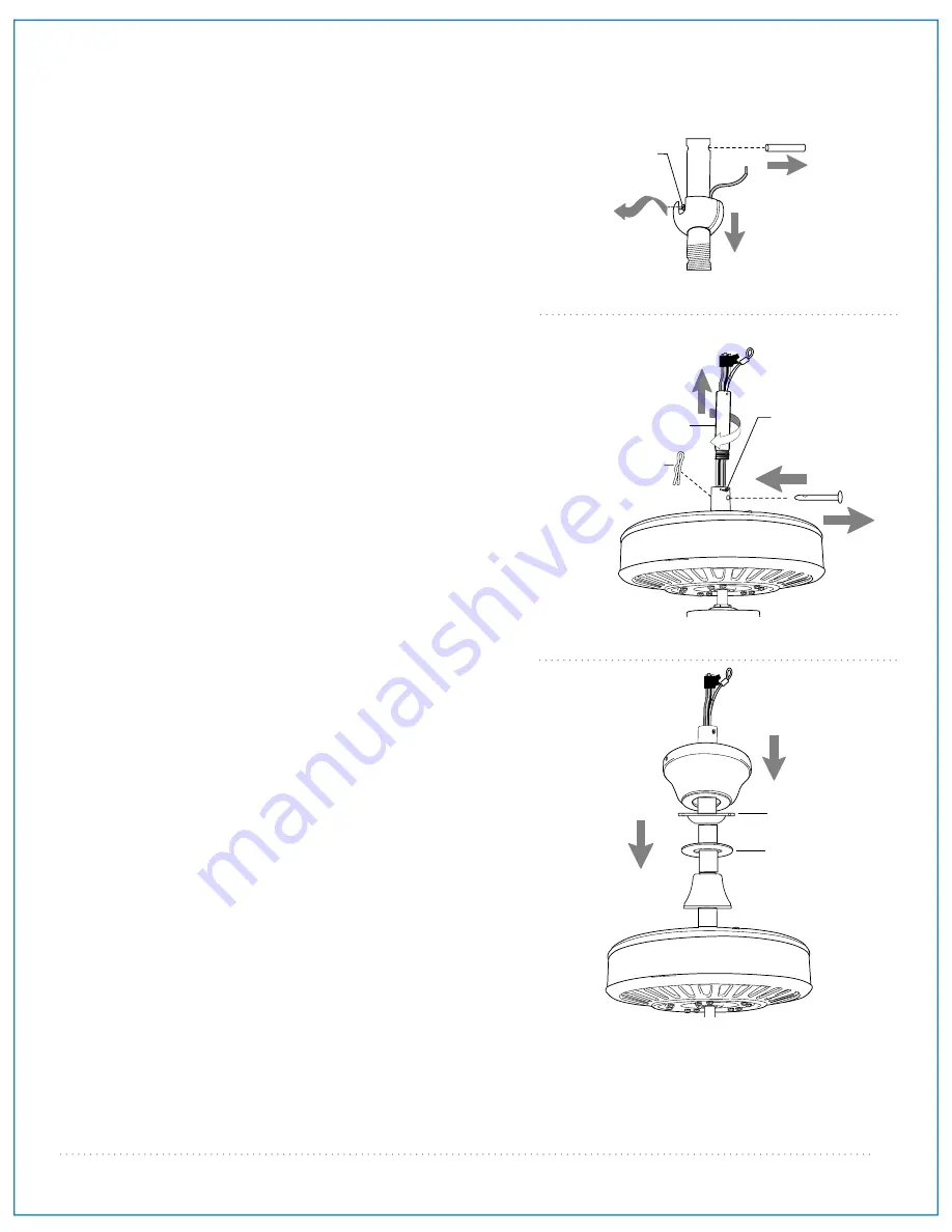
Remove hanging ball from downrod provided by 
loosening set screw on hanging ball. Lower 
hanging ball and remove stop pin and then slide 
hanging ball off of the downrod. [

Refer to 

diagram 1

.

]

Loosen yoke set screws and nuts at top of motor 
housing. Remove pin and clip from motor housing 
yoke. [

Refer to 

diagram 2

.

]

Tip

: To prepare for threading electrical wires 

through downrod, apply a small piece of electrical 
tape to the ends of the electrical wires--this will 
keep the wires together when threading them 
through the downrod. [

Refer to 

diagram 2

.

]

Determine the length of downrod you wish to use. 
Thread safety cable and electrical wires through 
threaded end of downrod and pull extra wire slack 
from the upper end of the downrod. [

Refer to 

diagram 2

.

Thread downrod into the motor housing yoke until 
holes for pin and clip in downrod align with holes 
in yoke--

make sure wires do not get twisted

Re-insert pin and clip that were previously 
removed. Tighten yoke set screws and nuts 
securely. [

Refer to 

diagram 2

.

]

 
Locate canopy cover and anti-sway adapter in 
hardware packs. Slide yoke cover, canopy cover, 
anti-sway adapter and canopy over downrod.  
[

Refer to 

diagram 3

.

] (

Note

: Canopy cover must be 

turned with shiny side 

toward

 motor housing. If 

using the anti-sway adapter, it must be turned with 
flat side 

toward

 the canopy.)

["Fan Assembly"  continued on next page.]

NOTE

:  The important safety precautions and instructions 

appearing in the manual are not meant to cover all possible 
conditions and situations that may occur. It must be 
understood that common sense and caution are necessary 
factors in the installation and operation of this fan.

yoke cover

anti-sway
adapter

canopy cover

Summary of Contents for OPXL52

Page 1: ...nging Bracket Installation pg 3 Fan Assembly pgs 4 5 Wiring pg 6 Canopy Assembly pg 6 Blade Assembly pg 7 Testing Your Fan pg 7 Troubleshooting pg 8 Parts Replacement pg 8 Warranty pg 8 net weight of...

Page 2: ...n must be connected to a supply circuit that is protected by a Ground Fault Circuit Interrupter GFCI to reduce the risk of personal injury electrical shock or death 5 Electrical diagrams are for refer...

Page 3: ...been included a canopy 1 piece b hanging bracket 1 piece c 6in downrod and hanging ball 1 piece d 3in downrod 1 piece e motor housing 1 piece f anti sway adapter in hardware pack 1 piece g weatherproo...

Page 4: ...ing bracket towards high point of ceiling Arrange electrical wiring around the back of the hanging bracket and away from the hanging bracket opening Note It is very important that you use the proper h...

Page 5: ...threaded end of downrod and pull extra wire slack from the upper end of the downrod Refer to diagram 2 Thread downrod into the motor housing yoke until holes for pin and clip in downrod align with hol...

Page 6: ...he end of the safety cable should just fit over the threads on the wood screw Test safety cable by pulling on loose end with pliers If the safety cable slips the loop must be adjusted tighter Extra ca...

Page 7: ...g can be made as follows Connect BLACK and BLUE wire from fan to BLACK wire from ceiling with wire connector provided Connect WHITE wire from fan to WHITE wire from ceiling with wire connector provide...

Page 8: ...weatherproof cover from reverse switch Attach pull chain extension supplied or custom pull chain extension sold separately to the end of the pull chain diagram 1 diagram 2 diagram 3 diagram 4 8 Blade...

Page 9: ...al purchaser any fan motor that fails to operate satisfactorily when failure results from normal use RETURN FAN MOTOR ONLY shipping prepaid to Craftmade Industries We will repair or ship purchaser a r...

Page 10: ...ador P gs 4 5 Instalaci n el ctrica P g 6 Colocaci n de la cubierta decorativa P g 6 Colocaci n de las aspas P g 7 Verificaci n del funcionamiento del ventilador P g 7 Localizaci n de fallas P g 8 Pie...

Page 11: ...ar ADVERTENCIA si va a utilizar este ventilador en un lugar MOJADO hay que conectar el ventilador a un circuito de alimentaci n que est protegido por un Interruptor de Circuito de Falla de Tierra GFCI...

Page 12: ...bo de 15 24cm y bola que sirve para colgar 1 unidad d tubo de 7 62cm 1 unidad e bastidor del motor 1 unidad f adaptador de estabilizaci n en paquete de art culos de ferreter a 1 unidad g cubierta a pr...

Page 13: ...gida hacia la parte alta del techo Arreglar el alambrado el ctrico los cables en la parte de atr s del soporte y lejos de la abertura del soporte Nota Es muy importante usar los art culos de ferreter...

Page 14: ...agrama 2 Enroscar el tubo en el cuello del bastidor del motor hasta alinearse los agujeros para el perno y la clavija en el tubo con los del cuello asegurarse de que no se tuerzan los cables Volver a...

Page 15: ...erta a prueba de la intemperie para la bola que sirve para colgar agujero para el tornillo de fijaci n tornillo de fijaci n cableado Ya que est sujetado el soporte de montaje a la caja de salida y cap...

Page 16: ...este ventilador no incluye juego de luz es necesario colocar un conector para cable en la punta del cable AZUL como se indica con la flecha en el diagrama Nota en cambio si elige comprar juego de luz...

Page 17: ...para la cadena de encendido provista a la cadena de encendido o usar una hecha a medida a la venta por separado 8 Colocaci n de las aspas bastidor del motor brazo para el aspa aspa tornillos y arandel...

Page 18: ...para acordar el reenv o del ventilador Devolver el ventilador con los gastos de env o prepagados a Craftmade Nosotros repararemos o reemplazaremos el ventilador y pagaremos los gastos de env o de regr...

Reviews: