background image

Summary of Contents for 102.249020

Page 1: ...eration Maintenance Repair Parts Espa_ol CAUTION Read and follow all Safety Rules and Operating Instructions before first use of this equipment For Customer assistance call the Sears Craftsman Helpline 1 800 659 5917 Mon Sat 9 30 am 9 30 pm CST Sears Roebuck and Co Hoffman Estates IL 60179 U S A ...

Page 2: ...rt symbol is used in decals on the unit and with proper operation and procedures in this manual Understand the safety message It contains important information about personal safety on or near the unit DANGER IMMINENTLY HAZARDOUS SITUATION If not avoided WILL RESULT in death or serious injury WARNING POTENTIALLY HAZARDOUS SITUATION If not avoided COULD RESULT in death or serious injury CAUTION POT...

Page 3: ...abilize the machine by putting your foot on the ground Do not use grass catcher on steep slbpes Do not operate on slopes over 10 maximum Do not park on slopes unless necessary When parking on slope always chock or block wheels Always set parking brake CHILDREN Tragic accidents can occur if the operator is not alert to the presence of children Children are often attracted to the machine and the mow...

Page 4: ... in maintaining caring for and using your Grass Catcher Follow the instruction under Maintenance and Storage sections of this Owner s Manual SPECIFICATIONS Model Number 102 249020 Clearing Width 40 101 6 cm with 40 Deck Sagg ng Capacity 6 Bushels 0 21 m3 Length Added to Unit 25 64 cm Width Added to Unit 3 7 6 cm Required Front Weight 45 Ibs 20 4 kg Read thls Owner s Manual and Safety Rules before ...

Page 5: ...TO BAGGER FRAME BAGGER TUBE HARDWARE SHOWN ACTUAL SIZE GROUPA INIIIlllllln _ 8 5 16 24x 75 8 5 16 24 BOLTS LOCKNUTS 4 VANES GROUP B I _ 2 44 14x4 5 CARRIAGE BOLTS I I 2 44 14 LOCKNUTS GROUP C i lll 1 1 2 13xl 0 BOLT 1 1 2 13 GROUPE LOCKNUT GROUPD __ II11 1 3 6 16xl 25 BOLT 1 3 8 16 LOCKNU I 4 _16 18Xlo0 BOLTS 4 5 16 18 LOCKNUTI _ 3 6 16xl O BOLTS GROUP F I lllllllll IIIllllll 4 3 8 16 LOCKNUT 1 5 ...

Page 6: ...wer deck from the unit Refer to the unit Owner s Manual for mower deck removal instructions WARNING Vanes MUST be used in pairs DO NOT interchange with different or worn vanes on same blade Using one of each of a different type or worn vane will cause blade to be out of balance and severe vibration will occur 2 Secure vanes on top of blade using hex bolts and top lock nuts provided Hex Bolt Locknu...

Page 7: ... brace loosened in step 3 11 Remove the bolt washer and nut holding the sup port strap to the seat support 12 Reinstall the shroud with the hardware saved from step 4 The bolt removed in step 11 should go through the washer shroud seat support then the support strap 13 Reinstall the dump valve knob and secure with jam nut Bagger Assembly 1 Install cover assembly onto bagger frame Use the two 5 16 ...

Page 8: ...s BaggerTube 1 Slide bagger tube into upper boot 2 Slide tube and hose clamp Group H over lower boot and tighten clamp to secure tube NOTE For removal instructions refer to storage section CAUTION Deflected material may cause injury ALWAYS operate mower with bagger cover closed and secured collector boot and tube fastened securely or with chute deflector in operating position Pull Pin r Boot 8 ...

Page 9: ...on slopes and abrupt turns or speed changes Front weight is required when using bagger OBJECTS MAY BETHROWN Stop blade rotation Mower Clutch Out before opening cover Check bagger components for structural damage wear or deterioration before each usage Replace only with original service parts 2 CAUTION Stop engine before removing tube boot or placing hand inside Do not run mower without complete tu...

Page 10: ...t operate mower with grass catcher partially installed Close and secure cover before starting Disengage mower when crossing driveways or gravel surfaces and other areas where thrown objects could be a hazard Do not attempt to vacuum up cans or other potentially hazardous projectiles Pre Start _ CAUTION ALWAYS check bagger parts for structural damage wear or deterioration before operation IMPORTANT...

Page 11: ...ard the rear off of the tube rails_ With the basket resting on the ground close and secure the top of the plastic lawn bag Tip the basket on its side and slide the filled bag from the basket I I _ 7 3 1 Center of Turning Radius 2 Maximum Bagger Sweep 3 UnitTurning Radius Lawn Conditions When operating your grass catcher on a lawn where grass and leaf bagging equipment has not been used you are pic...

Page 12: ...ce control levers in NEUTRAL position Set parking brake Place PTO in DISENGAGED position Turn ignition key to OFF position and remove key Make sure blades and all moving parts have completely stopped Disconnect spark plug wires from spark plugs and place wires where they cannot come in contact with plugs CAUTION Grass catcher components are subject to wear damage and deterioration which could expo...

Page 13: ...L A WARNING Tractor must be used with entire grass catcher system in place If using tractor to mulch or side discharge entire grass collection system must be removed To Remove bagger from unit Refer to assembly illustrations Remove lower boot and bagger tube Unhook and raise cover Slide baskets out Remove wing nuts holding cover assembly to bagger frame and remove cover assembly Remove vanes from ...

Page 14: ...TS 40 INCH MOWER GRASS CATCHER MODEL NUMBER 102 249020 DECALS WARNING 1 DECALS KEY PART NO QTY NO 1 07748400 1 2 07748500 1 3 07897700 1 DESCRIPTION Decal WARNING EZR Bagger Decal Craftsman Decal CAUTION Boot 14 ...

Page 15: ...CRIPTION NO Upper Boot 12 02746300 2 Pull Pin Hose Clamp 13 06807200 6 Rivet Tubular 187 x 375 Hose 7 x 38 14 05970500 8 Bolt Hex 31 24 x 75 Grade 8 Lower Boot 15 53504600 I Vane Service Package Rivet Tubular 187 x 375 16 06537000 8 Nut Locking Top 312 24 Extension Chute 17 06442700 10 Washer Flat Steel 219 x 50 TubeRetainer Clip x 049 Rivet Pop 187 x 527 18 53602100 1 Mower Boot assembly 40 Rivet...

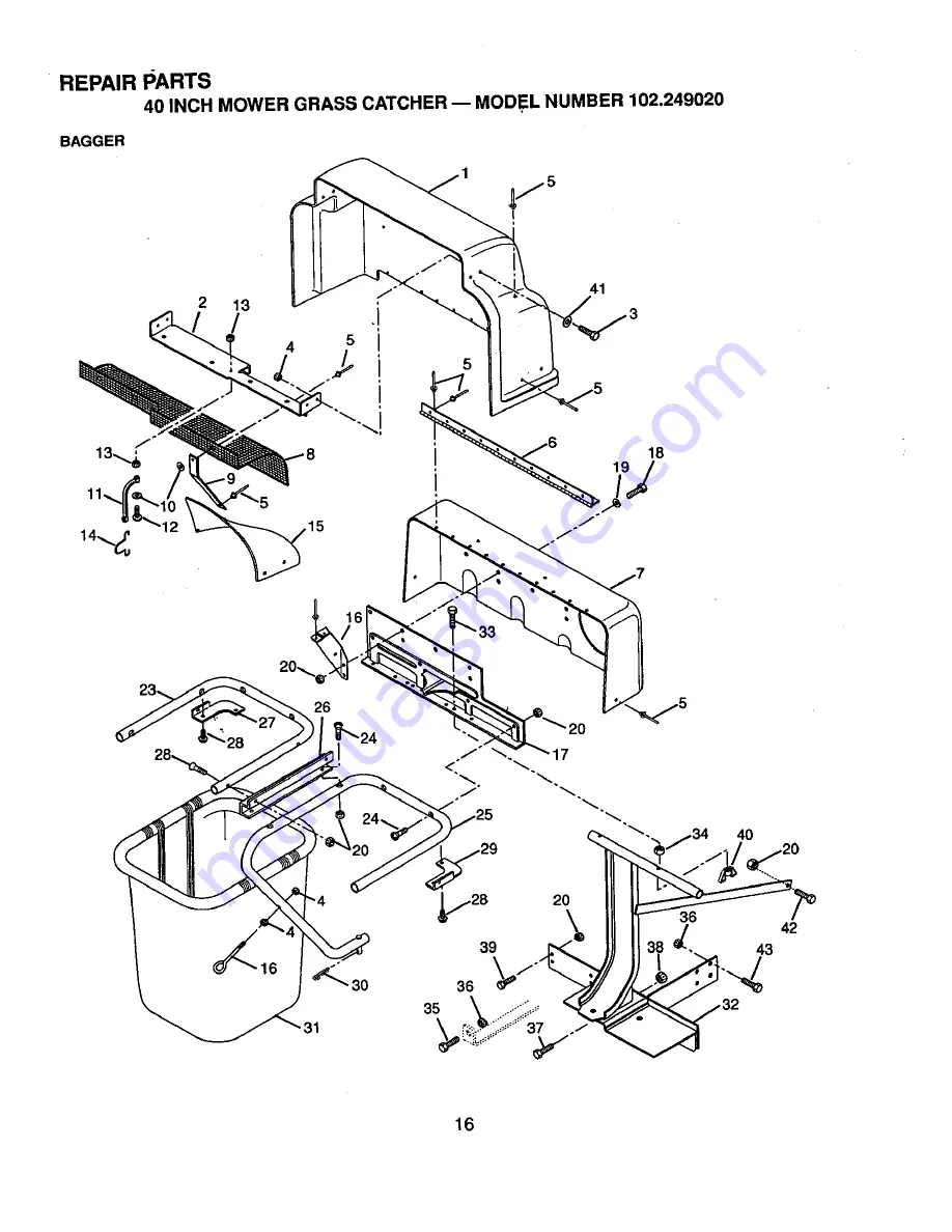
Page 16: ...REPAIR PARTS 40 INCH MOWER GRASS CATCHER MODEL NUMBER 102 249020 BAGGER I 2 13 i I 41 4O V28 39 36 2O 42 43 16 ...

Page 17: ...trap 1 Screw Machine 10 24 x 88 2 Nut Locking Top 10 24 1 Hook 1 Baffle 1 Eyebolt 1 Mounting Bracket 6 Bolt Hex 31 18 x 88 Grade 2 6 Washer Flat Steel 344 x 1 125 x 063 19 Nut Locking 312 18 2 Brace 9 _ Rivet Pop 187 x 527 1 Center Tube 8 Screw Machine 31 18 z 1 50 1 RightTube 1 Tube Bracket 1 Left Hand Corner Bracket 4 Screw Tapping 312 18 x 50 1 Right Hand Corner Bracket 1 Pin Hair Internal 08 x...

Page 18: ......

Page 19: ......

Page 20: ...455 For the repair or replacement parts you need Call 6 am 11 pm CST 7 days a week PartsDirect s 1 800 366 PART 1 8o_36_7278 Para ordenar piezas con entrega a domicilio 1 800 659 7084 For the location of a Sears Parts and Repair Center in your area Call 24 hours a day 7 days a week 1 800 488 1222 To purchase or inquire about a Sears Maintenance Agreement Call 7 am 5 pm CST Monday Saturday 1 800 82...

Reviews: