background image

Summary of Contents for 113.24201

Page 1: ...3 24201 CAUTION Read SAFETY iNSTRUCTIONS carefully CRRFr 1dgH 12 INCH BAND SAW SANDER assembly operating repair parts SEARS ROEBUCK AND CO Chicago IL 60684 U S A and SIMPSONS SEARS LIMITED Toronl Part No 69079 Printed In U S A ...

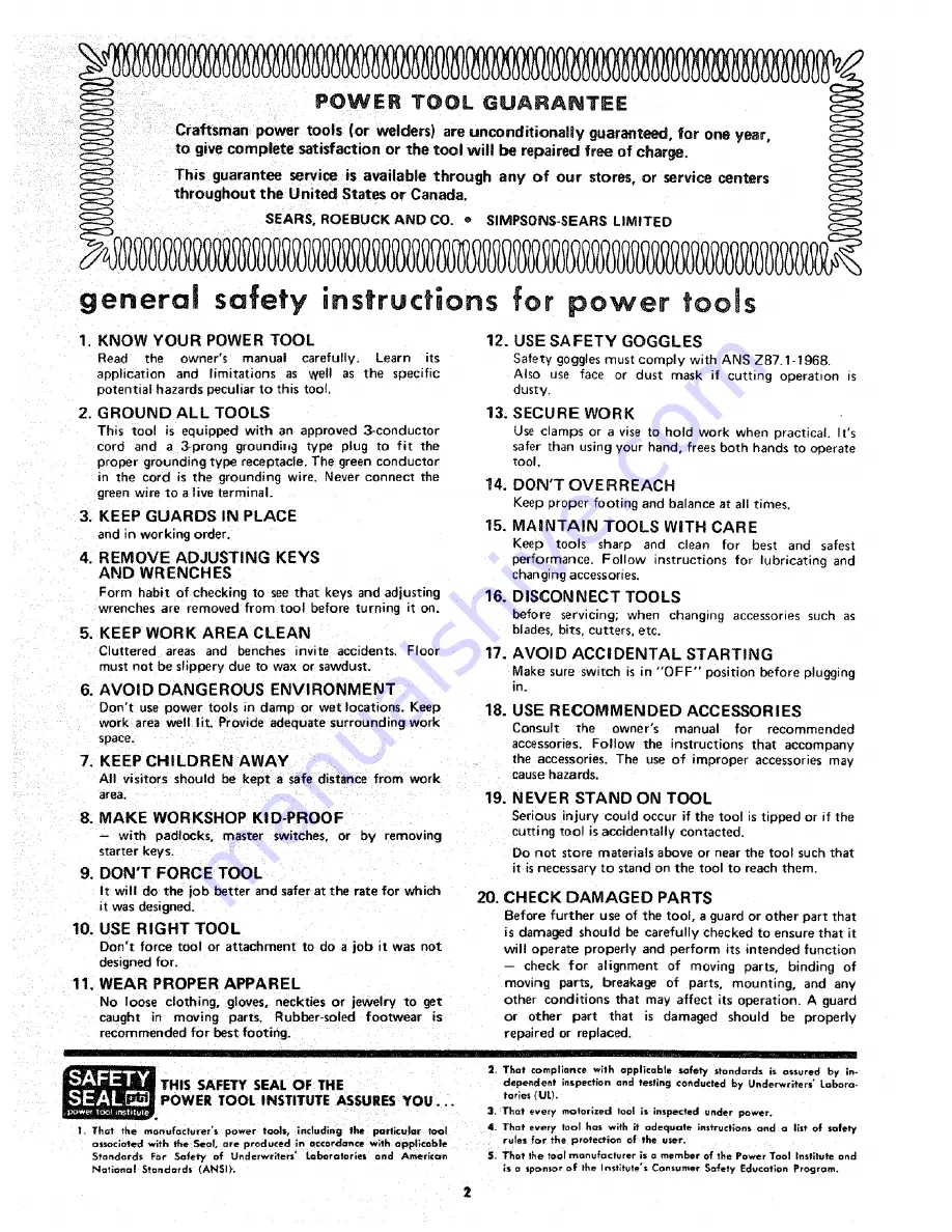
Page 2: ...wner s manual for recommended accessories Follow the instructions that accompany the accessories The use of improper accessories may cause hazards 19 NEVER STAND ON TOOL Serious n jury could occur if the tool istippedor if the cutting tool is accidentally contacted with padlocks master switches or by removing starter keys 9 DON T FORCE TOOL It will do the iob better and safer at the rate for which...

Page 3: ...ngers away from the blade k Use caution when cutting off material which is ir regular in cross section which could pinch the blade before the cut is completed A piece of molding for example should lay flat on the table and no_ be per mitted to rock while being cut Use caution when cutting off round material such as dowel rods or tubing They have a tendency to roll while being cut causing the blade...

Page 4: ...MATELY 900 RPM OR 2700 FEET PER MINUTEI WHEN USED WITH A 1725 RP_ MOTOR NEVER SUBSTITUTE THESE PULLEYS TO INCREASE THIS SPEED BECAUSE IT COULD BE DAN GEROUS WARNING DO NOT ALLOW FAMILIARITY GAINED FROM FREQUENT USE OF YOUR BAND SAW TO BECOME COMMONPLACE ALWAYS REMEMBER THAT A CARELESS FRACTaON OF A SECOND IS SUFFI CIENT TO iNFLICT SEVERE iNJURY 4 ...

Page 5: ...d and grounding type plug which has a grounding prong approved by Underwriters Laboratories and the Canadian Standards Association The ground conductor has a green jacket and is attached to the tool housing at one end and to the ground prong in the attachment plug at the other end This plug requires a mating 3 conductor grounded type outlet as shown If the outlet you are planning to use for this p...

Page 6: ... one carton w_thout rno or or floor basel Separate all oarts from packing materials and check each i ern w_th Ilustratlon and Table of Loose Parts Make certain all items are accounted for before discarding any paekinq material Key TABLE OF LOOSE PARTS Qty N0 1 Bas_e Saw Assembly 1 2 Owner s Manual 1 3 Saw Table 1 4 1 2x 52 1n V Belt 1 5 Carton containing Belt Guard Belt Guard Support 6 Support Bra...

Page 7: ...osition the stiffner furnished with base as shown 5 Insert the two 2 bolts through the holes in the right foot and through the holes in the stiffner 6 Place a flat washer Iockwasher and a nut on these bolts from underneath Do not tighten the nuts LEFT FOOT_ CHECK BOLTS FOR STIFFNER 7 Place the 1 1 8 diameter flat washer on the 3 bolt and insert the bolt in the hole in the left foot Place a flat wa...

Page 8: ...n 2 Screw both of the self threading screws into the holes to cut the threads and then remove them 3 Place the elbow in the opening and attach the clamp with the two screws CLAMP SAWDUST ELBOW RUBBER GASKET 4 Peel off the protective covering from the rubber gasket and stick it around the clamp Make sure it extends a little beyond each end of the clamp The gasket will help to prevent sawdust from l...

Page 9: ... so that the two trunnion pins and the table lock bolt go through the slot in the trunnion 2 Find the 1 I 8 dia flat washer a sleeve 11 16 long the trunnion lock nut and the table lock handle from among the loose parts 3 Hold the head of the table lock bolt inside the band saw with your left hand and put the 1 1 8 dia flat washer the sleeve and the handle on the bolt 4 Screw the nut on the bolt an...

Page 10: ...sing a double shaft motor the 5 8 dia shaft must be facing you BELT GUARD SU PPORT BRACKET THREAD CUTTING SCREWS BELT GUARD SUPPORT 2 Attach guard support to the bracket with the two screws furnished with the guard NOTE The holes in the bracket arenot threaded but the screws are thread cutting screws and will cut a thread as they are tightened SCREWS 10 ...

Page 11: ..._J___ _ _ MOTOR _ FLUSH HERE SHAFT KEY 3 16x 3 16 KEY L ADAPTER SLEEVE 112 DIAo MOTOR SHAFT CHECK MOTOR ROTATION The motor must rotate COUNTERCLOCKWISE when viewed from the PULLEY end I Place the motor on your workbench or on the floor 2 Stand clear of the motor and plug the cord into a pro perly grounded outlet See page 4 Notice the rotation of the pulley If it is not turning COUNTERCLOCK WISE RE...

Page 12: ...her and a Iockwasher on each holt screw on nuts but DON T TIGHTEN them 4 Loosen the two BELT GUARD SUPPORT SCREWS 5 Loosen the two MOTOR BASE CLAMP SCREWS and rotate the motor so that the ventilation holes are facing downward tighten the screws 6 Tighten the BELT GUARD SUPPORT SCREWS MOTOR MOUNT BRACKET c _ L J_ _ _c _ BELT GUARD SUPPORT SCREWS _ _ VENTILATION HOLES FACING DOWNWARD MOTOR BASE CLAM...

Page 13: ...ttach the belt guard support with the three screws fur nished with the guard NOTE The support bracket is not required The holes for attaching the support are not threaded but the screws are self threading and will cut a thread as they are screwed in SELF THREADING SCREW 2 Replace the pulley with the hub flush with the end of the shaft FLUSH HERE 13 ...

Page 14: ...n the belt guard 90 apart with the long tabs pointing AWAY from the round opening 4 Insert one looped end of belt all the way into guard so that it will be below motor pulley OPEN END _ _ SPRING CLIPS _ _ SET 90 APART 5 Snap the guard into position as shown 14 ...

Page 15: ...tor bolt nuts NOTE It is only necessary to tension the belt so that it does not slip while running If you cannot obtain sufficient tension with the motor pushed all the way down remove the four motor bolts and insert them in the LOWE R set of holes BLADE TENSION KNOB iNSTALLING THE BLADE 1 Find the blade tension knob among the loose parts Put a dab of grease or vaseline on the end of the knob and ...

Page 16: ...nches above the table and tighten the knob GUIDE BAR LOCK KNOB GUIDE BAR UPPER BLADE __ 4 Loosen the two setscrews which lock the upper blade guides and separate them about 1 8 Do that same thing to the lower guides beneath the table UPPER THRUST BEARING 1 8 SETSCREW WR ENCH _ SETSCR EWS BLADE GUIDE 16 ...

Page 17: ...r ing and turn knob until the thrust bearing is all the way back THRUST BEARING ADJ KNOB 1 8 SETSCREW WRENCH BLADE GUIDE 6 Loosen the setscrew which locks the lower thrust bear ing and turn the knob until the thrust bearing is all the way back LOWER THRUST BEARING SETSCREW 17 ...

Page 18: ... adjustment screw clockwise about 1 4 of a turn as though you were tightening it If the blade moves toward the back of the band saw a Turn the tracking adjustment screw counterclock wise about 1 4 of a turn as though you were loosen mg it Turn the screw just enough to cause the blade to run in the approximate center of the tire TRACKING ADJUSTMENT SCREW BLADE CENTERED ON TIRES OF BOTH WHEELS The t...

Page 19: ...nd place it in the opening in the table 22 Replace the cover Y liII SAW BLADE _UPPER BLADE GUIDE _ _TABLE ALIGNMENT SCREW ADJUSTING THE TABLE 1 Locate among the loose parts a 5 16 18 x 3 8 socket head flat point setscrew and a knurled head screw The knurled head screw keeps the table in align ment Screw it into the tapped hole underneath the front edge of the table 2 The socket head screw acts as ...

Page 20: ...THAT MOTOR ROTATION IS CORRECT SEEPAGE 11 The On Off Switch has a locking feature TH S SHOULD PREVENT UNAUTHORIZED AN D POSSIBLY HAZAR DOUS USE BY CHILDREN AND OTHERS 1 Insert key into switch NOTE Key is made of yellow plastic 2 To turn machine on insert finger under switch lever and pull end of switch out 2O ...

Page 21: ...h other hand WARNING FOR YOUR OWN SAFETY AL WAYS LOCK THE SWITCH OFF WHEN MACHINE iS NOT IN USE REMOVE KEY AND KEEP IT IN A SAFE PLACE ALSO IN THE EVENT OF A POWER FAILURE ALL OF YOUR LIGHTS GO OUT TURN SWITCH OFF LOCK II AND REMOVE THE KEY THIS WiLL PREVENT THE MACHINE FROM STARTING UP AGAIN WHEN THE POWER COMES BACK ON 5 Connect motor cord to outlet on back of band saw RD OUTLET 21 ...

Page 22: ...nstalling a 1 4 wide blade tighten the tension knob until the pointer is pointing to the 1 4 marking 4 TABLE TILTING Loosen the table lock handle tilt the table to the desired angle and tighten the lock handle To return the table to the 90 position tilt it until the 90 stop screw rests on the frame then tighten the lock handle 5 6 7 8 BLADE GUIDE ADJUSTMENT Turning the knob moves the guides in ol ...

Page 23: ...ort are larger than the screws This allows the support to be moved 5 Move the guide bar until it is square with the table then tighten the screws _ _ _ __ SCREW _ IIlIIA L _Y WRENCH iNSTALLING SANDING ATTACHMENT WARNING FOR YOUR OWN SAFETY TURN SWITCH OFF AND ALWAYS REMOVE PLUG FROM POWER SOURCE OUTLET BEFORE INSTALLING SANDING ATTACHMENT 1 Remove the blade guard the table insert and the table ali...

Page 24: ...ck knob and lower the end of the sanding platen below the table PLATEN 9 Locate among the loose parts the insert with the wide slot the alignment plate a flat head machine screw 6 32 x 7 16 a small hex nut and Iockwasher k SANDING CENTER OF S PLATEN TABLE IN 10 Attach the alignment plate to the insert so that the end of the alignment plate is in the center of the slot in the insert Place the inser...

Page 25: ...n ferrous metals SAWING 1 Adjust the upper guides not more than 1 4 above your workpiece 2 Use both hands while feeding the work into the blade Hold the workpiece firmly against the table Use gentle pressure and do not force the work but allow the blade to cut 3 The smallest diameter that can be cut out is determined by the width of the blade For example a 1 4 wide blade will cut a minimum diamete...

Page 26: ...guides or the thrust bearings Clean them with Crafts Tan Gum and Pitch Remover CAUTION Do not immerse the thrust bearings Apply a thin coat of automobile type wax on the table so that the wood slides easily while cutting MOTOR Frequently blow out any sawdust from the motor If the power cord is worn or cut or damaged in any way have it replaced immediately For motor maintenance follow instructions ...

Page 27: ... see Assembly approximate center of the correctly on shaft Section Installing the Blade lower wheel Band Saw slows down when cutting Blades breaking 1 Belt too loose 2 Motor pivots in motor base 3 Cutting too small a radius 4 Dull blade 1 Too much tension 2 Kink in blade caused by cutting too small a radius or turning the material too fast when cutting 1 Adjust belt tension see Assembly Section At...

Page 28: ...oo CRAFTSMAN 12 INCH BAND SAW SANDER MODEL 113 24201 8 ia 2 4 14 SEE FIGURE 2 FOR EXPLODED VIEW 10 3fi 40 39 38 ...

Page 29: ...ed with Set Screw Clip S Guard Belt otBett V Type 1 2 x 43 fBelt V Type 1 2 x 52 tPutley 1 2 V Groove 2 1 2 x 5 8 Bore Keyed with Set Screw Bracket Support Support Belt Guard Screw 5116 18 x I Sems Hex Hd Foot Right Nut Square 5 16 18 Standard Hardware Item May Be Purchased Locally FIGURE 1 PARTS LIST KEY PART NO NO 25 69053 26 STD522503 27 69023 28 65013 29 69004 30 STD601103 31 69078 32 69059 33...

Page 30: ...CRAFTSMAN 12 tNCH BAND SAW SANDER MODEL 113 24201 B 0 Q a_ Q 21 8 I 20 19 14 FIGURE 2 ...

Page 31: ...elf Locking 5 16 18 x 3 8 Standard Hardware Item May Be Purchased Locally tStock Item May t_ secured through the Hardware Department of most Order Houses oSupplied in Canada only KEY NO 42 43 44 45 46 47 48 49 5O 51 52 53 54 55 56 57 58 59 60 61 62 63 64 65 66 67 69 70 71 72 73 74 75 76 77 78 79 80 PART NO 69039 69045 STD551031 38825 STD502505 STD522505 STD315505 69038 STD522507 STD551t25 69041 ST...

Page 32: ...es will be furnished on re quest or parts will be shipped at prevailing prices and you will be billed accordingly WHEN ORDERING REPAIR PARTS ALWAYS GIVE THE FOLLOWING INFORMATION AS SHOWN IN THIS LmST 1 The PART NUMBER 3 The MODEL NUMBER 113 24201 2 The PART DESCRIPTION 4 The NAME OF ITEM CRAFTSMAN 12 INCH BAND SAW SANDER Your Sears merchandise takes on added value when you dis cover that Sears ha...

Reviews: