background image

Summary of Contents for 137.212390

Page 1: ...low all its Safety Rules and Operating Instructions Safety Instructions Installation Operation Maintenance Parts List Customer Help Line For Technical Support 1 800 843 1682 Sears Parts Repair Center 1 800 488 1222 Sears Roebuck and Co Hoffman Estates IL 60179 USA Visit our Craftsman website www sears comlcraftsman Part No 137212390001 Printed in China ...

Page 2: ...om lead based paints Crystalline silica from bricks cement and other masonry products Arsenic and chromium from chemically treated lumber Your risk from these exposures varies depending on how often you do this type of work To reduce your exposure to these chemicals work in a well ventilated area and work with approved safety equipment such as dust masks that are specially designed to filter out m...

Page 3: ...and all bystanders must read and understand Operator s manual before using this product KEEP HANDS AWAY FROM BLADE Failure to keep your hands away from the blade will result in serious personal injury SUPPORT AND CLAMP WORK IA DANGER J IA WARNING J IA CAUTION l ICAUTION I DANGER indicates an imminently hazardous situation which if not avoided will result in death or serious injury WARNING indicate...

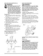
Page 4: ...g hair 12 ALWAYS WEAR EYE PROTECTION Any O ower tool can throw foreign objects into the eyes and could cause permanent eye damage ALWAYS wear Safety Goggles not glasses that comply with ANSI Safety standard Z87 1 Everyday eyeglasses have only impact resistant lenses They ARE NOT safety glasses Safety Goggles are available at Sears NOTE Glasses or goggles not in compliance with ANSI Z87 1 could ser...

Page 5: ...til the blade comes to a complete stop and the tool is unplugged from the power source 21 DO NOT OVERREACH Keep proper footing and balance at all times 22 MAINTAIN TOOLS WITH CARE Keep tools sharp and clean for best and safest performance Follow instructions for lubricating and changing accessories 23 WARNING Dust generated from certain materials can be hazardous to your health Always operate saw ...

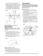
Page 6: ...ompleting the cut release the trigger and wait for the blade to stop before returning the saw to the raised position 1 MAKE SURE the blade has come to a complete stop before removing or securing the workpiece changing the workpiece angle or changing the angle of the blade 20 NEVER cut metals or masonry products with this tool This miter saw is designed for use on wood and wood like products 21 NEV...

Page 7: ...akers may trip frequently if a MOTOR is overloaded overloading can occur if you feed too rapidly or make too many start stops in a short time b LiNE VOLTAGE is more than 10 above or below the nameplate voltage rating For heavy loads the voltage at motor terminals must equal the voltage specified on the nameplate c iMPROPER or dull saw blades are used 5 Most motor troubles may be traced to loose or...

Page 8: ...ars A WARNING Read warnings and conditions on your CARBIDE TIPPED SAW BLADE Do not operate the saw without the proper saw blade guard in place Carbide is a very hard but brittle material Care should be taken while mounting using and storing carbide tipped blades to prevent accidental damage Slight shocks such as striking the tip while handling can seriously damage the blade Foreign objects in the ...

Page 9: ... carry handle 2 Place the saw on a secure stationary work surface 3 Separate all parts from the packing material Check each one with the illustration to make certain all items are accounted for before discarding any packing material I_WARNING if any part is missing or damaged do not attempt to assemble the miter saw or plug in the power cord until the missing or damaged part is correctly replaced ...

Page 10: ...Hold down Clam Sliding Guide insert Left Table Mounting Hole Base Positive Stop Locking Lever Stop Latch Knob Carrying Laser ON OFF Switch Slide Carriage Lock Knob ON OFF Trigger Switch Motor Positive Miter Detents ht Extension Table Table Lock Knob p Plate ...

Page 11: ... right MOUNTING HOLES To mount the miter saw to a stable surface ON OFF TRIGGER SWITCH To start the tool squeeze the trigger Release the trigger to turn off the miter saw POSITIVE STOP LOCKING LEVER Locks the miter saw at a preset positive stop for the desired miter angle SWITCH HANDLE The switch handle contains the trigger switch and the laser on off switch The blade is lowered into the workpiece...

Page 12: ...UTTING HEAD FIG D Unlocking _ WARNING To avoid injury and damage to the saw transport and store the miter saw with the cutting head locked in the down position Never use the stop latch to hold the cutting head in a down position for cutting operations 1 Push down slightly on the switch handle 1 2 Pull out the stop latch knob 2 3 Allow the cutting head to rise to the up position Fig D Locking When ...

Page 13: ...ll small pieces of material from the table cavity before performing any cuts The table insert may be removed for this purpose but always reattach the table insert prior to performing a cutting operation Do not start the sliding compound miter saw without checking for interference between the blade and table insert Damage could result to the blade table insert or turntable if blade I _ WARNING To a...

Page 14: ...ING OR INSTALLING THE BLADE Removing Blade Fig K L and M 9 Remove the arbor bolt 4 the arbor collar 6 and the blade 7 Do not remove the inner blade collar Fig M 10 Raise the lower clear plastic blade guard 1 to the upright position Fig K to remove the blade _ WARNING To avoid injury from an accidental start make sure the switch isin the OFF position and plug is not connected to the power source ou...

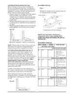
Page 15: ...ally loosens and helps prevent the spinning blade from coming off the saw o Make sure the collars are clean and properly arranged Lower the blade into the table and check for any contact with the metal base or the turn table Your tool is equipped with the Laser Trac cutting guide using Class II laser beam The laser beam will enable to preview the saw blade path on the stock to be cut before starti...

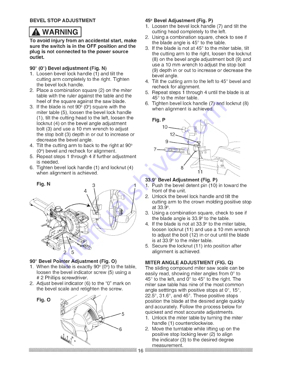
Page 16: ... 4 Tilt the cutting arm to the left to 45 bevel and recheck for alignment 5 Repeat steps 1 through 4 until the blade is at 45 to the miter table 6 Tighten bevel lock handle 7 and Iocknut 8 when alignment is achieved Fig P 8 33 9 Bevel Adjustment Fig P 1 Push the bevel detent pin 10 in toward the front of the unit 2 Unlock the bevel lock handle and tilt the cutting arm to the crown molding positive...

Page 17: ...blade and the ruler against the fence 2 asshown 4 Adjust the fence 90 tothe blade and tighten the four fence locking bolts CAUTION Ifthe saw has notbeen used recently recheck blade squareness tothe fence and readjust if needed 5 After fence has been aligned using a scrap piece of wood make a cut at 90 then check squareness on the piece Readjust if necessary Fig R 1 2 1 _t_ _s_ 2 ADJUSTING CUTTING ...

Page 18: ...saw is missing bent damaged or broken in any way or any electrical parts don t work turn the saw off and unplug it Replace bent damaged missing or defective parts before using the saw again Maintain tools with care Keep the miter saw clean for best and safest performance Follow instructions for lubricating Do not put lubricants on the blade while it is spinning Remove adjusting wrench from the too...

Page 19: ...vise to help hold the work when it s practical USE EXTRA CAUTION WiTH LARGE OR ODD SHAPED WORKPIECES Use extra supports tables sawhorses blocks etc for workpieces large enough to tip Never use another person as a substitute for a table extension or as an additional support for a workpiece that is longer or wider than the basic miter saw table or to help feed support or pull the workpiece Do not us...

Page 20: ...op Unplug the miter saw Fig U c i i i i i i i i i i i J f _ I t _ 4 5 K y 3 L 8 3 4 in 8 3 4 in 1 BASIC SAW OPERATIONS I A WARNING For your convenience your saw has a blade brake The brake is not a safety device Never rely on it to replace the proper use of the guard on your saw If the blade doesn t stop within approximately 10 seconds wait for the blade to stop unplug the saw and contact customer...

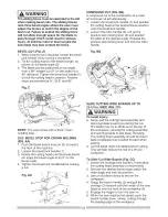
Page 21: ...void injury from materials being thrown always unplug the saw to avoid accidental starting and remove small pieces of material from the table cavity MITER CUT FIG Y 1 When a miter cut is required unlock the miter table by turning the miter handle 1 counterclockwise 2 While holding the miter handle lift up on the positive stop locking lever 2 3 Rotate the miter table to the right or left with the m...

Page 22: ...45 Fig Z NOTE The saw comes with a 33 9 crown molding stop 33 9 BEVEL STOP FOR CROWN MOLDING FIG AA 1 Push the bevel detent stop pin 2 in toward the front of the machine 2 Loosen the bevel lock handle 1 3 Rotate the cutting head until the bevel detent pin stops the bevel angle at 33 9 on the bevel scale 4 Tighten the bevel lock handle before making a cut Fig AA Fig BB SLIDE CUTTING WIDE BOARDS UP ...

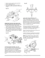
Page 23: ...of the saw or into the blade guard and housing possibly causing damage or injury To minimize this an auxiliary wood fence can be mounted to your saw Holes are provided in the saw fence to attach an auxiliary wood fence This fence is to be constructed of straight wood approximately 3 4 in thick by 2 1 2 in high by 18 in long Attach the wood fence securely and make a full depth cut to make a blade s...

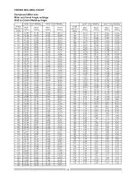
Page 24: ...lding has a top rear angle the section that fits flat against the ceiling of 52 and a bottom rear angle the section that fits flat against the wall of 38 In order to accurately cut crown molding for a 90 inside or outside corner lay the molding with its broad back surface flat on the saw table When setting the bevel and miter angles for compound miters remember that the settings are interdependent...

Page 25: ... 66 13 32 12 20 11 93 90 31 62 33 86 35 26 30 00 147 10 34 12 93 11 83 11 59 91 31 17 33 53 34 79 29 71 148 10 01 12 54 11 46 11 24 92 30 73 33 19 34 33 29 42 149 9 69 12 16 11 09 10 89 93 30 30 32 86 33 86 29 13 150 9 37 11 77 10 73 10 55 94 29 86 32 51 33 40 28 83 151 9 05 11 38 10 36 10 20 95 29 43 32 17 32 94 28 54 152 8 73 10 99 10 00 9 85 96 29 00 31 82 32 48 28 24 153 8 41 10 60 9 63 9 50 9...

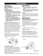
Page 26: ...ard They could make the plastic cloudy and brittle When cleaning the lower guard unplug the saw from the power source receptacle to avoid unexpected start up SAWDUST Periodically sawdust will accumulate under the worktable and base This could cause difficulty in the movement of the worktable when setting up a miter cut Frequently blow out or vacuum up the sawdust l _ WARNING if blowing sawdust wea...

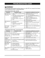
Page 27: ...re start i2 Brush worn i3 Fuse blown or circuit breaker tripped on home panel Brush spark il Brush worn when switch i2 Other released TROUBLESHOOTING GUIDE SAW OPERATION PROBLEM PROBLEM CAUSE SUGGESTED CORRECTIVE ACTION Blade hits table 1 Misalignment 1 See ADJUSTMENT Setting Cutting Depth section Angle of cut not 1 Miter table unlocked 1 See OPERATION Miter Angle accurate Can 2 Sawdust under tabl...

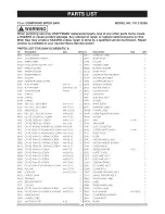
Page 28: ...VOT 2C81 LINEAR MOTION BEARING 2CGT SLOTTED SETSCREW 2D92 CONTROLLER ASS Y 2DX9 SEGMENT HANDLE 2E63 ROCKER SWITCH 2EXC LOCATION PiN 2F39 CLEVIS PiN 2F8Y DUST BAG ASS Y 2F9N STICKER 2GYC SHAFT SLEEVE 2K96 WARNING LABEL 2MGR POWER CABLE 2MN9 LASER PLUNGER HOUSING 2PWU MOTOR 2PY1 ARM AW 2PY4 ARM MITER 2PYE DUST COLLECTOR 2PYG CUTTER SHAFT GUARD AW 2PYJ SHAFT PIVOT 0KA9 CR RE PAN HD TAPPING SCREW M3 2...

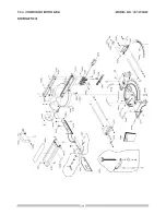
Page 29: ...12 in COMPOUND MITER SAW SCHEMATIC A MODEL NO 137 212390 i ...

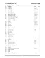
Page 30: ...KQW LOCK NUT M5_0 8 T 5 0KQX NUT M6 1 0 T 6 0KR4 LOCK NUT M8 1 25 T 8 2258 SPECLAL BOLT 2754 WARNING LABEL 20S3 LOCKLNG HANDLE ASS Y 20X5 ASSBT FENCE AW 25TD MLTER BAR 25TE STOP BLOCK LEFT 23 25TF STOP BLOCK RLGHT 23 27BU TABLE LNSERT 27BV TABLE LNSERT 2C8U KNOB 2CD2 COMPRESDON SPRLNG 2DAN REAR EXTENTLON STAY 2DWL PLUNGER HANDLE 2DWP NEEDLE POLNTER 23 2F76 FENCE AW 2K8Q WARNING LABEL 2LSZ VLSEASS ...

Page 31: ...12 in COMPOUND MITER SAW SCHEMATIC B MODEL NO 137 212390 _ ...

Page 32: ...0Q9K FLOW GUIDE 0QGR COMPRESSION SPRING 0QMK RUBBER CAP 0QMY PROTECTOR WIRE 0QQS BRUSH HOLDER ASS Y 0QQT BRUSH ASS Y 0QR0 BRUSH COVER 0OR2 BEARING BUSHING 2lAX CLEVIS PIN 23Z3 GEAR BOX 23Z4 MOTOR HOUSING 240R ARMATURE ASS Y 27DB CUTTER SHAFT ASS Y 2B79 CR RE PAN HD SCREW WASHER 2PXT FIELD ASS Y 2QOP LEAD WIRE ASS Y Size cp4 30 M5 0 8 6 M5_0 8 12 M5 _ 12 60 M5 g 8 6 AW M5_g 8 35 QTY 1 2 3 2 2 2 2 2...

Page 33: ......

Page 34: ...rHome For repair of carry in items like vacuums lawn equipment and electronics call anytime for the location of your nearest Sears Parts Repair Service Center 1 800 488 1222 U S A 1 800 469 4663 Canada www sears com www sears ca To purchase a protection agreement on a product serviced by Sears 1 800 827 6655 U S A 1 800 361 6665 Canada Pard pedir servicio de reparacion Au Canada pour service en fr...

Reviews: