background image

Summary of Contents for 137.218760

Page 1: ...60_ CAUTION Before using this Table Saw read this manual and follow all its Safety Rules and Operating Instructions Safety Instructions Installation Operation Maintenance Parts List EspaSol Customer Help Line 1 800 843 1682 Sears Roebuck and Co Hoffman Estates IL 60179 USA Part No 137218760001 ...

Page 2: ...nly for 90 days from the date of purchase This warranty gives you specific legal rights and you may also have other rights which vary from state to state Sears Roebuck and Co Dept 817 WA Hoffman Estates IL 60179 MOTOR Maximum developed HP 2 5 Volts 120 Amperes 13 Hertz 60 RPM no load 5000 Overload protection YES SAW Table 17 1 8 x 26 Blade 10 Maximum depth of cut at 90 3 Maximum depth of cut at 45...

Page 3: ... moving parts Nonslip footwear is recommended Wear protective hair covering to contain long hair ALWAYS WEAR EYE PROTECTION Any table saw can throw foreign objects into the eyes which could cause permanent eye damage ALWAYS wear Safety Goggles not glasses that comply with ANSI safety standard Z87 1 Everyday eyeglasses have only impact resistant lenses They ARE NOT safety glasses Safety Goggles are...

Page 4: ...nd sides of the saw table for wide or long workpieces 13 AVOID KICKBACKS work thrown back towards you by keeping the blade sharp keeping the rip fence parallel to the saw blade and by keeping the spreader anti kickback pawls and guard in place and functioning Do not release work before it is pushed all the way past the saw blade Do not rip work that is twisted warped or does not have a straight ed...

Page 5: ...r should be used only until a properly grounded receptacle can be installed by a qualified technician The adapter FIGURE B has a rigid lug extending from it that MUST be connected to a permanent earth ground such as a properly grounded receptacle box The Canadian Electrical Code prohibits the use of adapters r_ k_v _ _ll _ _ CAUTION In all cases make certain the receptacle is properly grounded If ...

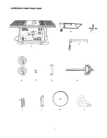
Page 6: ...recommended by Sears TOOLS NEEDED Medium screwdriver Adjustable wrench 2 Phillipsscrewdriver I I Ill I till I I t _ _ i _ _ _i4 _i_ Straight edge Combination square To avoid personal injurty if any parts are missing or damaged do not attempt to assemble the table saw plug in the power cord or turn the switch on untilthe missing or damaged part is obtained and is installed correctly TABLE OF LOOSE ...

Page 7: ...UNPACKING YOUR TABLE SAW A C e e 1 G H K L ...

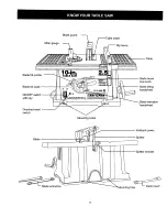
Page 8: ...lt pointer l in TABLE SAW Table Blade tilt scale ON OFF switch with key Overload reset switch Blade bevel lock knob Blade tilting handwheel Blade elevation handwheel Mounting holes Blade J Kickback pawls Splitter plitter bracket _nches Mounting hole 8 ...

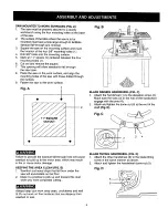
Page 9: ...he work surface Fig A 1 l 2 Fig B BLADE RAISING HANDWHEEL FIG C 1 Attach the handwheel 1 to the elevation screw 2 Make sure the slots 3 in the hub of the handwheel engage with the pins 4 2 Attach and tightenthe dome nut 5 at the end of the shaft Fig D Fig C 3 2 4 1 P_Eig Zld_l_ Failure to provide the sawdust fall through hole will cause sawdust to build up in the motor area which may result in fir...

Page 10: ...G G to the maximum height by turning the blade raising handwheel counterclockwise 3 Remove the arbor nut 5 and flange 6 remove blade 4 Install the new saw blade onto the arbor with the blade teeth pointing toward the front of the saw 5 Install the flange 6 against the blade and thread the arbor nut 5 as far as possible by hand Ensure that the blade is flush against the inner side of the blade flan...

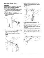
Page 11: ... table and tighten NOTE Blade guard and splitter assembly removed from the splitter bracket illustration for clarity in FIG J Fig J Check that the nuts 7 that hold the blade guard assembly 8 to the bracket 4 are tight Tighten if necessary FIG K Fig K 6 Position the blade guard arm 9 FIG L to the rear 7 Using a straight edge check to see that the blade guard splitter 10 is aligned with the saw blad...

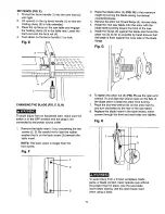
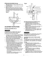
Page 12: ...the handle 2 upward and turn the adjusting screw 5 clockwise until the rear clamp is snug Do not turn the adjusting screw more than 1 4 turn at a time Over tightening the adjusting screw will cause the fence to come out of alignment Fig N 8675 2_ RIP FENCE INDICATOR ADJUSTMENT FIG N 1 The rip fence indicator 6 points to the measurement scale 8 The scale shows the distance from the side of the fenc...

Page 13: ...ial cut on scrap wood when making critical cuts Measure for exactness Fig P BLADE PARALLEL TO MITER GAUGE GROOVE FIG Q R This adjustment was made at the factory but it should be rechecked and adjusted if necessary To prevent personal injury Always disconnect plug from the power source when making any adjustments This adjustment must be correct or kickback could result and accurate cuts cannot be m...

Page 14: ...Fig S 3 2 TILTINGTHE BLADE FIG S To tilt the saw blade for bevel cutting loosen the lock knob 2 and turn the tilting handwheel 3 Tighten the lock knob 2 to secure ON OFF SWITCH FIG T The ON OFF switch has a removable key With the key removed from the switch unauthorized and hazardous use by children and others is minimized 1 To turn the saw ON insert key 1 into the slot inthe switch 2 Move the swi...

Page 15: ...ble saw to cause careless mistakes Remember that even a careless fraction of a second is enough to cause a severe injury Keep both hands away from the blade and path of the blade The workpiece must have a straight edge against the fence and must notbe warped twisted or bowed 1 Remove the miter gauge Secure the rip fence to the table 2 Raise the blade so it is about 1 8 higher than the top of the w...

Page 16: ...t side groove 2 Adjust the blade height so it is 1 8 higher than the top of the workpiece 3 Hold the workpiece firmly against the miter gauge with the blade path in line with the desired cut location Move the workpiece to one inch distance from the blade 4 Start the saw and wait for the blade 1 to come up to full speed 5 Keep the workpiece 2 against the face of the miter gauge 3 and flat against t...

Page 17: ... ripping material such as thin paneling to prevent the material from catching between the bottom of the fence and the table _3 F 2 The dado table insert is included with this saw Remove saw blade blade guard installed dado and dado table insert Instructions for operating the dado are packed with the separately purchased dado set The arbor 1 on this saw restricts the maximum width of the cut to 1 2...

Page 18: ...ade raising mechanism and tilting mechanism should be checked for looseness binding or other abnormalities With the saw disconnected from the power source turn the saw upside down and alternately pull upward and downward on the motor unit Observe any movement of the motor mounting mechanism Looseness or play in the blade raising screw 1 should be adjusted as follows 1 Using a wrench loosen nut 2 2...

Page 19: ...eed Machine vibrates excessively Does not make accurate 45 and 90 cross cuts 1 Dull blade 2 Blade mounted backwards 3 Gum or pitch on blade 4 Incorrect blade for work being done 5 Gum or pitch on table causing erratic feed 1 Rip fence out of alignment 2 Splitter not aligned with blade 3 Feeding stock without rip fence 4 Splitter not in place 5 Dull blade 6 The operator letting go of material befor...

Page 20: ... Toothed washer 6 1 20 2501NZDN 16 Flat washer 1 4 x 3 4 1 64 1 21 1420500 Splitterbracket 1 22 2701FBD106 Hex nut M6 x 1 0 T 5 2 23 14914901 Washer D 18 2 24 2604BBLA42 Screw M6 x 1 0 25 3 25 2636BZDBA9 Screw M6 x 1 0 50 3 26 2801ABRGO 1 Rubber washer 6 1 1 27 2621BZDA18 Cap hd screw M5 x 0 8 12 1 28 14903101 Insert 1 29 2621BZDA18 Cap hd screw M5 x 0 8 12 1 30 2636BZDB48 Cr re count hd screw M6 ...

Page 21: ...CRAFTSMAN 10 TABLE SAW FIGURE A A MODEL NO 137 218760 cO 21 ...

Page 22: ... 85 2853U55501 Breaker switch 1 86 14902302 Switch box 1 87 2801 DBHA04 Strain relief RC 1632 2 a p n screw 89 83990121 Clamp cord 1 90 2801ABRF01 Strain relief 11 1 91 18402702 Rubber pad 4 92 14903104 Dado insert 1 93 14905604 Plate cover 1 94 2690MZD515 Rivet 5 11 3 95 14911402A2 Miter Gauge Assembly includes key 58 66 1 96 14014801 Hex wrench 1 97 14904402 Open wrench 1 98 2138MBL704 Allen wre...

Page 23: ...CRAFTSMAN 10 TABLE SAW MODEL NO 137 218760 FIGURE B C33 7 23 ...

Page 24: ...A 16 1 3 5 49 s s 02 136 14935001 Nut 1 137 2701FBD106 Hex nut M6 x 1 0 T 5 2 138 2502ABC417 Spring washer 6 2 139 2501NBDN09 Washer 1 4 x 3 4 7 64 1 140 2701FZD106 Hex nut M6 x 1 0 T 5 1 141 14922901 Spacer 1 142 2672BZDA44 Cap hd sq neck bolt M6 x 1 0 35 1 143 2701FBD106 Hex nut M6 x 1 0 T 5 2 144 15210601 Bearing seat 2 145 14936301 Shatt 1 146 14935902 Stiffener 1 147 2672BBDB50 Rod hd squ nec...

Page 25: ...CRAFTSMAN 10 TABLE SAW FIGURE C MODEL NO 137 218760 25 ...

Page 26: ...26 ...

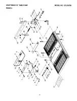
Page 27: ... _ _ Z Q ffJ 27 ...

Page 28: ...28 ...

Page 29: ...I l I I I I I J J J j J I I j _ 0 Io J I I ___o _o I I f C J J o w o _ 0 0 C D C_ _ _ 0_ o I I oo 0 o 29 ...

Page 30: ...30 ...

Page 31: ...ut microscopic particles ADVERTENCIA I El polvo originado por el uso de lijadoras sierras moledoras taladros y pot algunas actividades relacJonadas con la construcci6n contiene qufmicos reconocidos como causantes de c_ncer malformaciones cong_nitas u otros da_os reproductivos Algunos ejempios de estos qufmicos son Plomo de las pinturas a base de plomo Silice cristalina proveniente de los ladritlos...

Page 32: ... le service ou les pi_ces For the repair or replacement parts you need Call 6 a rn 11 p m CST 7 days a week PartsDirect TM 1 800 366 PART 1 800 366 7278 Para ordenar piezas con entrega a domicilio 1 800 659 7084 For the location of a Sears Service Center in your area Call 24 hours a day 7 days a week 1 800 488 1222 To purchase or inquire about a Sears Maintenance Agreement Call 7 a m 5 p m CST Mon...

Page 33: ...ABLE SAW _ F CUIDADO Antes de usar esta Sierra de Mesa leer este manual y seguir todas sus Reglas de Seguridad e Instrucciones de OperaciSn Instrucciones de Seguridad InstalaciSn OperaciSn Mantenimiento Lista de Partes Tel6fono para Ayuda al Cliente 1 800 843 1682 Sears Roebuck and Co Hoffman Estates IL 60179 USA Part No 137218760001 ...

Page 34: ...ompra Estagarantia te otorga derechos legales especfficosy tambi_n podria usted tener otros derechosque varian de un estado a otro Sears Roebuck and Co Dept 817 WA Hoffman Estates IL 60179 MOTOR Caballaje maximoquedesarrolla 2 5 HP Voltios 120 Amperios 13 Hertzios 60 RPM Sincarga 5000 Protecci6n de sobrecarga SI SIERRA Mesa 17 1 8 x26 43 5 cm x 66 cm Hoja 10 25 4 cm Profundidadm_ima de corte a 90 ...

Page 35: ...tahara un mejortrabajo y mas segurous_ ndola s61oen laforma para la querue disefiada USARLA HERRAMIENTA ADECUADA No forzarla herramienta al haceruntrabajoparael cual no ha sido disefiada USAR EL CORDONDE EXTENSIONADECUADO Cerciorarseque el cord6n de extensionest_en buenas condiciones AIusaruncord6nde extensi6n cerciorarse que seaIosuficientementegruesoparaconducir la corriente que la maquinava a d...

Page 36: ...CESO pieza de trabajo aventadade regreso al operador manteniendola hoja filosa la barrera paralelaa la hoja y manteniendoel soporte separador el trinqueteantiretrocesoy la cubierta protectora de la hoja en posici6ny en buenas condicionesde trabajo No soltar la pieza de trabajo hasta haberla hechopasar completamentepor la hojade la sierra No cortar maderas que est6n torcidas arqueadas onduladaso qu...

Page 37: ...en forma permanentea tierra tal como la caja de un tomacorrientedebidamenteconectado a tierra El C6digo Electrico Canadienseprohibe el uso de estos adaptadores CUIDADO En todoslos casos cerciorarseque el tomacorriente en cuesti6neste adecuadamenteconectado a tierra Si nose estuviese seguro hacerque unelectricista licenciado inspeccione el tomacorriente Fig A Enchufe de 3 espigas Espiga para conexi...

Page 38: ...os no recomendadospor Sears HERRAMIENTAS NECESARIAS Desarmador piano mediano Desarrnador en cruz 2 Illl Irllt II I Regla Llave regulable l l l l l l l l l _ TTT3 TTTTT Escuadra combinada Paraevitar riesgos de lesiones si faltasen piezas o hubiesen piezas daSadas no intentarenchufarla sierra ni activar el interruptorhasta conseguirlas piezasfaltanteso reemplazarlas daSadasy hasta haberlas instalado...

Page 39: ...DESEMBALAJE DE LA SIERRA DE MESA lO in A C 6 1 F G H I J K L 37 ...

Page 40: ... la hoja Escala de inclinaci6n de la hoja Interruptor con Ilave Bot6n reposicionador del interruptor de sobrecarga lO in TABLE SAW Manija de fijaci6n del l _ de la hoja _ _ _ Manivela elevadora _ de la hoja Orificios de montaje _ta hoja Tr nquetes antiretroceso Soporte separador IBisagra del soporte separador Orifncto de mo_rPara 38 ...

Page 41: ...la superficie de trabajo Fig A 2 Fig B 9 9 _v MANIVELAELEVADORADE LA HOJA FIG C 1 Instalarla manivela 1 en el v_ stagoroscado 2 Cerciorarse que las ranuras 3 en la bridade la manivela enganchenen las espigas 4 2 Ajustar la tuerca 5 en el extremo delv_ stago roscado Fig D Fig C 3 2 4 1 tY _1 J_vJ 1 II i 1 _ _ r No proveera la sierra un orificio en la supefficiede trabajo para la caida del aserrin p...

Page 42: ...mogirando la manivelaelevadoracontra el sentido del reloj 3 Sacar la tuerca del eje portahoja 5 y la brida 6 remover la hoja 4 Instalarla nuevahoja de la sierra en el eje portahojacon los dientes apuntando hacia abajo en el frente de la sierra 5 Instalar la brida 6 contra la hojay enroscar la tuercadel eje portasierra 5 al mdximo que se pueda a mano Cerciorarse que la hoja quede a ras con la brida...

Page 43: ...posteriorde la mesa de la sierray ajustarlo NOTA Para mayorclaridad el conjuntode cubierta protectoray soporteseparador no se han representadoen esta figura Fig J Verificarque las tuercas 7 que sujetanel protector 8 de la hoja del soporte separador 4 est6n ajustadas Ajustar si fuese necesario Fig K 8 6 Colocarel brazo del protector de la hoja 9 FIG L en la parte de atrds 7 Usando una regla verific...

Page 44: ...l medidor del dngulo de corte en inglete 4 Si se necesita hacer ajustes para poner la barrera paralelaa la ranura hacer Io siguiente Aflojar los dos pernos 3 y levantarla manija 2 Sujetar el soportede la barrera 4 firmementecontra el frente de la mesa de la sierra Moverel extremo m_ s alejado de la barrerahasta que quede paraleloa la ranurapara el medidor del _ ngulode corte en inglete Ajustar amb...

Page 45: ...colocarel puntero indicador sobre la marca de 0 y ajustarel tornillo NOTA Cuando se vayana hacer cortes crfticos medir la precisi6ndel corte haciendo un corte de pruebaen un retazo de madera de desecho 345 Paraevitar lesionespersonales Siempre desenchufarel cord6n del tomacorrienteantes de hacer cualquier regulaci6n Esta regulaci6ndebeajustarse para que quede correcta o la sierra pateara la pieza ...

Page 46: ...esen bisel aflojar el seguro de fijaci6n 2 y girarla manivelainclinadora 3 Luego ajustarel segurode fijaci6n 2 INTERRUPTOR FIG T El interruptortieneuna Ilaveque se puedesacar Cuando la Ilave no est_ en el interruptorse minimiza el riesgo de uso no autorizado y peligrosopor niSos u otras personas 1 Paraactivar la sierra insertar la Ilave 1 en la ranura del interruptor 2 Subirla Ilavea la posici6n d...

Page 47: ...cuidos Recordarque una fracci6n de segundo de descuidoes suficientepara causar una lesi6n severa Mantenerambas manosalejadas de la hoja y del camino de la hoja La pieza de trabajodebe tener un borde recto apoyadocontra la barreray no debe estararqueada ondulada ni torcida 1 Desmontarel medidor para cortes en inglete Fijar la barrera a la mesa 2 Subir la hoja hasta que quede a 3mm 1 8 sobre la piez...

Page 48: ...Sacar la barrerade la mesay colocar el medidor para corte en inglete en la ranuraizquierda de la mesa 2 Subir la hoja hasta que quedea 3mm 1 8 sobre la pieza de trabajo 3 Sujetar la pieza de trabajofirmemente contrael medidor para cortes en inglete alineandoel lugar del corte en la pieza con la hoja Moverla pieza de trabajo hastaque quede a 2 5cm 1 de la hoja 4 Ponerla sierra 1 en marchacolocando ...

Page 49: ...ta hoja Cerciorarseque el eje portahoja 3 quede ajustadoy que por Io menos una vuelta de roscadel eje sobresaigade la tuerca 5 Usarjuegos de hojas ranuradorasde 15cm 6 y mantener el ancho del corte a 12 7mm 1 2 o menos Ser_ necesario sacar la cubierta protectora de la hoja y el soporte separador cuando de usen los juegos de hojas ranuradoras Tener cuidadocuando se hacen cortes con el juego de hoja...

Page 50: ...eraci6n inspeccionarel mecanismo de elevaci6ne inclinaci6nde la hoja para detectarsi hay piezassueltas pegadas o con algunaotra anormalidad Con la sierra desenchufadadel tomacorriente dar vuelta de cabeza a la sierray subir y bajar la unidad del motor repetidamente Observar si el mecanismode montaje del motortiene alg_n juego Si los pernos de elevaci6n 1 tuviesen alglJnjuego deben ajustarse de la ...

Page 51: ...sina pegada a la mesa hacen que el avancede la pieza sea err_ttico 1 Barreradesalineada 2 Soporteseparadornoest alineadocon lahoja 3 Se est avanzandola pieza de trabajo prescindi_ndode la barrera 4 El soporte separador no esta instalado La Diezade trabajo rebota de la hoja 6 Reemplazarla hoja El operadorest _soltando la pieza de trabajo antes que termine de pasar por la hoja La perilla de regulaci...

Page 52: ...x M6 x 1 0 50 1 19 2504MZC006 Arandela dentada 6 1 20 2501NZDN 16 Arandela plana 1 4 x 3 4 1 64 1 21 14205001 Soporte separador 1 22 2701FBD106 Tuerca hex M6 x 1 0 T 5 2 23 14914901 Arandela D 18 2 24 2604BBLA42 Perno tornillo M6 x 1 0 25 3 25 2636BZDBA9 Perno tornillo M6 x 1 0 50 3 26 2801ABRG01 Aranclela de caucho 6 1 1 27 2621BZDA18 Perno cabeza de tornillo M5 x 0 8 12 1 28 14903101 Inserto 1 2...

Page 53: ...SIERRA DE MESA DE 10 FIGURAA MODEL NO 137 218760 cO o3 A I iii31_ d_ ilii i i difi _ IP _ d k 51 i ...

Page 54: ...lo autoenroscante M4 x 18 10 4 85 2853U55501 Interru ptorde circuito 1 86 14902302 Caja gel in errujotor 1 2 88 2660MBCE 14 Tornillo autoenroscante M4 x 16 16 2 89 83990121 Grapa para cord6n 1 90 2801ABRF01 Bujealiviador de tensi6n 11 1 91 18402702 Alrnohadilla de caucho 4 92 14903104 _serto para ranurar 1 93 14905604 _ubierta cte placa 1 94 2690MZD515 Remache 5 11 3 95 14911402A2 Medidor de ingle...

Page 55: ...SIERRA DE MESA DE 10 FIGURA B cD MODEL NO 137 218760 co 0 o o o o cO 53 ...

Page 56: ... 14935102 Placa de soporte 1 136 14935001 Tuerca 137 2701FBD106 Tuerca hex 138 2502ABC417 Arandela de presi6n 139 2501NBDN09 Arandela 140 2701 FZD106 Tuerca hex 141 14922901 Espaciador 142 2672BZDA44 Perno cab tornillo cuello cuadrado 143 2701FBD106 Tuerca hex 144 15210601 Asiento de cojinete 145 14936301 Eje 146 14935902 Refuerzo 147 2672BBDB50 Perno cab tornillo cuello cuadrado 148 2536MBE621 Cl...

Page 57: ...SIERRA DE MESA DE 10 FIGURA C MODEL NO 137 218760 55 ...

Page 58: ...microscopic particles _1_ ADVERTENCiA J El poivo originado por el uso de lijadoras sierras moiedoras taladros y por algunas actividades relacionadas con la construcci6n contiene qufmicos reconocidos como causantes de c_ncer malformaciones cong_nitas u otros da_os reproductivos Algunos ejemplos de estos qufmicos son Piomo de las pinturas a base de plomo S lice cristalina proveniente de los ladrilio...

Page 59: ...tout le service ou les pi_ces For the repair or replacement parts you need Call 6 a m 11 p m CST 7 days a week PartsDirect 1 800 366 PART 1 800 366 7278 Para ordenar piezas con entrega a domicilio 1 800 659 7084 For the location of a Sears Service Center in your area Call 24 hours a day 7 days a week 1 800 488 1222 To purchase or inquire about a Sears Maintenance Agreement Call 7 a m 5 p m CST Mon...

Reviews: