background image

Summary of Contents for 137.219120

Page 1: ...RESS Model No 137 219120 CAUTION Before using this Drill Press read this manual and follow all its Safety Rules and Operating Instructions Safety Instructions Installation Operation Maintenance Parts List Espa_ol Customer Help Line 1 800 843 1682 Sears Roebuck and Co Hoffman Estates IL 60179 USA Part No 137219120001 ...

Page 2: ...ection Your drill press is wired at the factory for 120V operation Connect to a 120V 5 AMP branch circuit and use a 15 AMP time delay fuse or circuit breaker To avoid shod or fire replace power cord immediately if it is worn cut or damaged in any way Some dust created by power sanding saw ng grinding drilling and other construction activities contains chemicals known to the State of California to ...

Page 3: ... TOOLS WITH CARE Keep tools sharp and clean for best and safest performance Follow instructions for lubricating and changing accessories 19 CHECK FOR DAMAGED PARTS Before further use of the tool a guard or other part that is damaged should be carefully checked to determine that it will operate properly and perform its intended function Check for alignment of movingparts binding of moving parts bre...

Page 4: ...s too short or the table is tilted clamp solidly to the table and use the fence provided SECURE WORK Use clamps or a vise to hold the work when practical It s safer than using your hand and it frees both hands to operate tool WHEN using a drill press vise always fasten to the table MAKE SURE all clamps and locks are firmly tightened before drilling SECURELY LOCK THE HEAD and table support to the c...

Page 5: ...on a circuit that has a receptacle like the one illustrated in FIGURE A FIGURE A shows a 3 prong electrical plug and receptacle that has a grounding conductor If a properly grounded receptacle is not available an adapter FIGURE B can be used to temporarily connect this plug to a 2 contact ungrounded receptacle The adapter FIGURE B has a rigid lug extending from it that MUST be connected to a perma...

Page 6: ...e drill press from moisture a protective coating has been applied to the machined surfaces Remove this coating with a soft cloth moistened with kerosene or WD 40 Use only accessories designed for this drill press to avoid injury from thrown broken parts or workpieces Do not use any accessory unless you have completely read the instruction or owner s manual for that accessory To avoid fire or toxic...

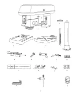
Page 7: ...F G H I J K L M N 0 P Q R 7 ...

Page 8: ... Motor pulley pulley Belt tension knob Feed spring Column collar Bevel scale Table support Support lock handle Base Bevel lock Fence end_ rod Depth stop Cover Table I Head lock screw _ to elt Head lock screw _Table crank handle Rack Fence backstop Column support ...

Page 9: ...ALE POINTER Indicates the drilling depth by pointing to the depth scale DEPTH SCALE STOP NUTS Locks the depth scale to selected depth DRILL ON OFF SWITCH Has locking feature This feature is intended to help prevent unauthorized and possible hazardous use by children and others Insert the key into the switch to turn the drill press on DRILLING SPEED Changed by placing the belt in any of the steps g...

Page 10: ...Make sure the worm gear 1 meshes with the inside gear 3 Insert the table support lock handle 4 into the hole at the rear of the table support Tighten NOTE Table removed from support in illustrationfor clarity Fig B _ 1 4 Place the rack 5 in position inside the table support 3 making sure the worm gear 1 on the inside of the table support is engaged with the teeth of the rack The Drill Press is ver...

Page 11: ... 5 on the column IMPORTANT The bottom of the collar MUST NOT be pushed all the way down onto the top of the rack MAKE SURE the top of the rack is under the bottom of the collar and that there is enough clearance to allow the rack to freely rotate around the column Tighten the set screw 8 CAUTION To avoid column or collar damage DO NOT OVERTIGHTEN the set screw Fig E The Drill Press is very heavy a...

Page 12: ...ush the chuck up onto the spindle 2 Tap gently to ensure seat 5 Open the jaws of the chuck 1 by rotating the chuck sleeve clockwise To prevent damage make sure the jaws are completely receded into the chuck Fig J 6 Using a rubber mallet plastic tipped hammer or a block of wood and a hammer firmly tap the chuck upward into position on the spindle shaft Fig K MOUNTING DRILL PRESSTOWORK SURFACE FIG L...

Page 13: ...rill Press Check alignment of the pulleys with a straight edge 5 such as a framing square a level or a piece of wood Lay the straight edge across the top of the pulleys If all three pulleys are NOT aligned 1 Release belt pressure by loosening the belt tension lock knobs 2 on either side of the head counterclockwise 2 Loosen the motor mount nuts 3 Lift or lower the motor 4 until the pulleys are in ...

Page 14: ...n the table to its original position loosen the bevel locking bolt 5 Realign the bevel scale 6 to the 0_ position 6 Return nut 4 on locking pin to the OUTSIDE END OF THREADS Gently tap lockingpin until it is seated in the hole Finger tighten nut 4 NOTE The table has been removed from the illustration for clarity Fig P 6 SPINDLE QUILL RG Q Rotate the feed handles counterclockwiseto lower spindle to...

Page 15: ...with the adjustable wrench If too loose repeat steps 2 through 5 to tighten If too tight reverse steps 4 and 5 DO NOT OVERTIGHTEN and restdct quill movement 7 Replace the jam nut 3 and tighten against the tandard nut 4 to prevent the standard nut from eversmg Fig R 3 4 To avoid injury from an accidental start ALWAYS make sure the switch is in the OFF position the switch key is removed and the plug...

Page 16: ... 5 If the switch key is removed while the ddllpress is running it can be turned OFF but cannot be restarted without insertingthe switch key Always lock the switch OFF when the drill press is not in use Remove the key and keep it in a safe place In the event of a power failure blownfuse or tripped circuit breaker turn the switch OFF and removethe key preventing an accidental startup when the power ...

Page 17: ... Workplece method FIG X and Y 1 Mark the depth of the hole on the side of the workpiece 1 2 With the switch OFF bdng the drillbit 2 down until the tip is even with the mark 3 Hold the feed handle at th s position 4 Spin the lower nut 3 down to contact the depth stop lug 6 on the head 5 Spin the upper nut 5 down and tighten against the lower nut 3 6 The drill bit will now stop after traveling the d...

Page 18: ...e table or provide auxiliary support i Use the fence provided or other fixtures for unusual operations to adequately hold guide and position workpiece j Use the SPINDLE SPEED recommended for the specific operation and workplace material Check the panel on the inside pulley cover or the chart below for drilling speed information For accessories referto the instructionsprovided with each accessory 5...

Page 19: ... drill down to align with the indentation before turning the drill ON TILTING THE TABLE FIGURE CC NOTE The table and support t has a predrilled hole with a locking pin inserted for locking the table into a predetermined 0 horizontal position 1 To use the table in a bevel tilted position TIGHTEN the nut 2 on the locking pin clockwise to RELEASE it from the table support 2 Loosen the large hex head ...

Page 20: ...side the motor A coat of automotive paste wax applied to the table and column will help to keep the surfaces clean To avoid shock or fire hazard if the power cord is worn or cut in any way have it replaced immediately LUBRICATION All of the drill press ball bearings are packed with grease at the factory They require no further lubrication Periodically lubricate the gear and rack table elevation me...

Page 21: ...ill bit Wood splinters on 1 No backup material 1 Use cackup material See Section underside under workpiece BASIC DRILL PRESS OPERATION Workpiece torn 1 Not supported or 1 Support workpiece or clamp it See Section loose from hand clamped properly BASIC DRILL PRESS OPERATION Drill bit binds in workpiece 1 Workpiece pinching drill bit 1 Support workpiece or clamp it See Section or excessive feed pres...

Page 22: ... qualified service technician Repair service is available at your nearest Sears Service Center Always order by PART NUMBER not by key number PARTS UST FOR SCHEMATIC A Key Part No 1 10300105 2A 10300202A2 3 2601BBDAg0 4 13902202 5A 10300603A11 6 10602003 7A 10302301A1 8A 10601009A3 9A 10838202A1 Description BASE COLUMN HOLDER ASS Y HEX SOC SET SCREW RACK TABLE BRACKET ASS Y TABLE LOCK HANDLE RACK R...

Page 23: ...CRAFTSMAN12 DRILL PRESS SCHEMATIC A MODEL NO 137 219120 A gA I 23 ...

Page 24: ...FBD113 HEX NUT M8x1 25 1 _ _ _ 0 _ _0i_ _PRIR_3RET _II_ER i t 31A 10305001A2 SPRING CAP ASS Y 1 32 2701QZD611_ HEX NUT I 2x20UNF 2 33 2668BBDA24 CR RE PAN HD SCREW M8 x 0 8 12 1 34 10808301 CLAMP CORD 1 35 10604204 SHIFTER BOLT 2 36 2603BBLA52 HEX SOC SET SCREW M8x1 25 8 2 37 2603BBLA52 HEX SOC SET SCREW M8x1 25 8 1 38 2536MBE623 SPRING PIN 2 39 13902503 HEAD 1 41_ 2_0 I I_B_ _ FIE XTR D _i31LT _ ...

Page 25: ...CRAFTSMAN12 DRILL PRESS SCHEMATIC B MODEL NO 137 219120 45 54A 35 11 it0 25 ...

Page 26: ...62 2572ARK340 V BELT 63 10306901 PULLEY SET NUT 6_4 10307005 SPINDLE PULLEY 65A 10306512A1 DRIVING SLEEVE ASS_ 66 13916602 LABEL Size 4 64 3 57 MODEL NO 137 2t912C Qty 1 1 1 1 2 1 1 1 1 1 67 2641BBDA39 68 10208302 69 2668BBDA23 70A 10307908A2 71 2571MNC307 72A 10409011A3 CR RE ROUND HD SCREW CLAMP CORD CR RE PAN HD SCREW MOTOR PULLEY ASS Y PARALLEL KEY PULLEY COVER ASS Y M6X1 0 12 4 4 4 1 1 1 26 ...

Page 27: ...CRAFTSMAN12 DRILL PRESS SCHEMATIC C MODEI NO 137 219120 59 71 70A 69 J 68 72A 64 65A 60 61 27 ...

Page 28: ...direct To purchase or inquire about a Sears Service Agreement 1 800 827 6655 7 a rn 5 p m CST Mon Sat Pard pedir serviciode reparaclbna domidlio Au Canada pour sewics en fran_ais y pard ordenar piezas con entmga a domicilio 1 877 LE FOYER 1 888 SU HOGAR TM 1 888 784 6427 SEARS o _ HomeCentrar _ P _ J Matca Registrada_ Mama de F_brk_ de Seam Roebu_ and CO FULL ONEyEAR WARRANTY If_ i_uCt failsduetOa...

Page 29: ...o 137 219120 CUIDADO Antes de usar esta Prensa Taladradora leer este manual y seguir todas las Reglas de Seguridad e instrucciones de Operaci6n Sears Roebuck and USA Part No 137219120001 0 Instrucciones de Seguridad Instalaci6n Operaci6n Mantenimiento Lista de Partes Tel6fono para Ayuda al Cliente 1 800 843 1682 Co Hoffman Estates IL 60179 ...

Page 30: ...o fusibie de etardode 15Amos S el cora6n elec rico estuvlese gas ado cortadoo dar_aao n cualquier form reempiazarto de Inmediatopara witar eleotrocuci0no Incendio TAMAI_IODE LA BASE 14 3 8 X 8 1 4 36 6cm X 21cm ALTURA 37 3 32 94 2cm Alogunos polvos creados por el lijado mec_mico el aserrado el esmedtado el taladrado y otras actividades de construccibn contienen sustancias quimicas conocidas pot le...

Page 31: ...cossodos recomendados El usode accesodos inapropiados puedeser peligroso yganerarriesgode lesionespersonales 15 16 17 18 NUNCA DEJAR DESATENDIDAUNA HERRAMIENTA ELI_CTRICACUANDO ESTE FUNCIONANDO DESCONECTARLA FUENTEDE ENERGIA Noalejarse del lugar hastaque la herramientase haya detenidopor completo NUNCA PARARSESOBRE LA HERRAMIENTA Pueden ocurnrlesiones sedassi la herramientase volteao si se entraen...

Page 32: ...guiaprovista 13 St LA PIEZA DETRABAJO seproyecta fuera de la mesa de formatal que se caigao inclinesi noestuviese sujeta sujetarta a la mesa o proveer unsoporte auxiliar RJAR LA PIEZA DE TRABAJO Cuandofuesaprdctico usarsargentas o una prensaparasujetar1_piezade tmbajo Esrods saguro queusarla manoy deia librearnbasmanos paraoperarla hermmienta AL USAR una prensa para taladro siempresujetariaa la me...

Page 33: ...uestJ6n est_adecuadamente conectado a tierra Si no se estuviese seguro hacerqueunelectficista licenciado inspeccione el tomacorriente EstaPrensaTaladradoraes_ disefiadaunicarnente parauso en interiores No exponeda ala Iluvianiusaria en lugares htimedos Fig A Enchufe de3 espigas _ _ _Tomacordente pare enchufe de3 espigas debidamente conectado atierra RECOMENDACIONES PAPALOS CORDONES DE EXTENSION Ce...

Page 34: ...lacionque est a continuaci6n Paraproteger ta PrensaTaladradora contrala humedad las partes maquinadas han siderecubiertas conunacapaprotectora que sedebe remover conun patiohumedecido conkerosene o WD 40 Paraevitarinoendioso reacciones tbxicas nuncausargasolina nafta acetona tinerparatacaso solventes simitares de alta volatilidad paralimpiarla PrensaTaladradora TABLE OF LOOSE PARTS ART DESCRIPCI6N...

Page 35: ...C D G H K 1 L M N 0 0 P Q 35 ...

Page 36: ...nclinacibn Soporte de la Mesa i de Profundidad de tope de avance Cubierta Protectora Tope de profundidad Interruptor Seguro del Soporte oe Ja Mess Base Seguro de la Inclinacibn de la Mesa Mesa Manijas de Avansa Segurode I Manij Tensionador de Correa Pernos de Fijaci6n del Cabezal Manivela de la Mesa Topedel Extreme de la Guia TopePosteriorde la Gula 36 Columna Soporte del a Columna ...

Page 37: ... Indica la profundidad del orificio que seestdtaladrando BROCA La herramienta quesa usa en Is PrensaTaladradora parahacerlosortfidosen la piezade tmbajo INTERRUPTORDELTALADRO riene undispositivo de seguro Estedispositivo estddisafiadopardevitarel usono autorizado y posiblemente peUgroso pornifiosy otraspersonas Iosertarla I_ve en el interruptor y girarlaparaponereltaladroen operaci6n VF LOCIDADDET...

Page 38: ...osoJatropernoshexagonales largos 3 en la bolsa conpiezas sueltas 4 Colocarunpemoen cada orifidodelsoportede la columna y de la base Ajustar con unaIlaveregulable Fig A I 2 3 Ens mbl je de la columna I meu Fig B F 1 Ubicarel eje de tomillosinfln la manivelade la mesay el segurodelsoportede la mesade la bolsade piezassueltas 2 Introducir el eje de tomiUo sinfln 1 en el oriflc_o 2 par la manivel de l...

Page 39: ...rporcompleto la parteinferior del anillosobrele partesuperior de la cremallera ASEGURARSEde que la partesuperior de la cremallera quededebajode la parte inferior del aniliny quehaya suficiente espaciolibreparaque la cremallerapuedagirarlibremente alrededorde la columna Aprleteet pemo_sionero 8 CUIDADO Pare evitardaf_ar la columnao el anillo NOAPRIETE EXCESIVAMENTEel pemopdsionero El cabezalde la P...

Page 40: ... mandibulas del mandril 1 girandotamangadel n_ndrilen el sen_dodel reloj Pareevitardefios cerciorarse quelas rnand_ulasest6ncompletamentemtra_das dentro delmandril Fig J _ I 3 Usandounmazodecauchoo martillo con cabezade pl_co o unbloquede maderayun martil_o go_peado levementehada arribahastaque enca eenposicibn en el eje FlCJ K COMO INSTALAR LAPRENSATALADRADORA A LA SUPERFICIEDE TRABAJO FIG L 1 Si...

Page 41: ...rificar etatinearniento de laspoleas conunaregla 5 escuadra nivelo pedazode maderarecta Colocarel horde de la reglaa Io largode la partesuperior de las poleas Si todas las poleasestuviesen desalineadas 1 Ativiar la tensi6nde las correasaflojando los segurosde las manijastensionadoras 4 de correasa cada ladodel cabezal desenganchando lasmanijastensionadoras 1 de correas 2 Aflojar1astuercas 2 de mon...

Page 42: ...arel pemogrendede cabezahexagonal que fija el _gulo de indinaci6n de la mesa r _lililli_iiiiil lll Pareevitarleelones cerciorarse de sujetarla mesa yel brazode la mesade telforma que nogirenisa incline 6 Alinearla escuadraconel v_go girendela mesahaste quela escuadrey el v_stagoquedenalineadas 7 Volvera ajustarel pemohexagonal grande 6 EJE MORTAJA RG Q Girarlasmanijasde avancecontrael sentidedelre...

Page 43: ...floja repetir los pasos 2 al 5 para ajustarla Si estuviesademasiado ajustada ejecutar los pasos 4 y 5 a la inversa Paraevitarlesiones debidas a unarranqueaccidental antesde hacer ajustes alas correas SlEMPREcerciorarse que el interruptoreste en la posicion OFF Apagado que la Ilavedel interruptorhaya side retiraday que el enchufeno estd conectado a tomacorriente TENSI _NDE LA CORREA FIG S Asegurars...

Page 44: ... 5 Si se retirala Ilavedelinterruptor cuandola Prensa Taladradora estaopemnOo estapodrbapagarseperoluego no podr_volversea prendersi nose insertala Ilave SIEMPREponede eeguroal interruptoren la posid6n OFF Apagade cuandola PrensaTaladradorano est_en uso Retirarla Ilavey mantenedaen un tugar seguro En caso de unafalla de suministro el_ctrico fusible _ladoo interruptorde circuiteabierto moverel inte...

Page 45: ...pagado girar la manija de avarice 2 hasteque el tope de profundidad 4 indique la pmfundidaddeseade en la escalade profundidad 6 y mantenerla manija de avariceen esa posici6n 2 Girar la tuerca inferior 3 bajandelahasta que haga contacto con el tope de profundidad 4 3 Girar la tuerca supedor 5 bajdndola hasteajustarlacontra la tuerca inferior 3 y ajustarla 4 La broca pararadespuds de bajar la distan...

Page 46: ...iezade trabajoenforma adecuadaen j Usarla VELOCIDADDE EJE recomendada parala oderacibn especffica y mater_al a taladrar Refedrseal panelen taparteinterior de ia cubiertade las poleaso a latablaque se indica a continuaci6n paraobtener informaci6n sobrelasvelocidadesde pedoracibn Para ootenerinformacibn sobrelosaccesorios refedrsealas instrucciones provistas concada accesorlo 5 Nuncasubirse a la mes...

Page 47: ...oportede la mesa girandoel pemo de fijaci6n 2 con una llave hexagonalcontrael sentido_del reloj 3 2 Aflojar el perno hexagonalgrandeque sujeta la mesa en el angulode inclinaci6n Fig AA Para evitarlesiones cerciorarsede sujetarel conjuntodel brazo y la mesa de modo tal que no gire ni se incline Fig CC J 2 3 ParapiezaspequeSasque nosepuedanfljara la mesacon sujetadores usarunaprensa parataladro acce...

Page 48: ...licaci6nde una capa de cera automotrizen pastaa la mesa y a la columna ayudar_ a mantenerlas superficieslimpias Para evitarlosriesgos de choque electricoo incendio si el cord6n electrico estuviesegastado o cortado repararloo cambiado de inmediato LUBRICACI N Todoslos cojinetes de bolas de la PrensaTaladradoravienen rellenos de grasa desde la fabrica No requierenlubricaci6n adicional Lubficar peri6...

Page 49: ... aceite en la superficie interior ahusada del mandril o en la superficie ahusada del eje SOLUCION 1 Regular la tension Ver la secci6n ENSAMBLAJE TENSION DE LA CORREA 2 Lubdcar el eje Ver la seccibn LUBRICACION 3 Asegurarseque la tuerca de retenci6nde la polea este ajustada y ajustada si fuese necesano 4 Ajustar el perno de fijaci6n de la poleadel motor 1 Cambiar la velocidad Ver la secci6n OPERACI...

Page 50: ...o calificado de servicio El servicio de reparaciones se encuentra disponible en el servicentro Sears mas cercano Siempre que deba solicitar piezas pidalas por su NOMERO DE PIEZA y no por su nl3mere clave USTA DE PIEZAS PARA EL DIAGRAMA A No Diag No Parte Descripcibn Tamafio Cantidad 1 10300105 Base 1 2A 10300202A2 Soporte de Columna 1 3 2601BBDA90 Perno Prisionero Hexagonal M8x1 25 25 4 4 13902202...

Page 51: ...NOMENCLATURE DE LA PERCEUSE A COLONNE DE 12 PO MODELE Nu 137 219120 DIAGRAMA A 7A 8A t I 51 ...

Page 52: ... _3 0 5 _i_ _ ff a _ f l_ _5_ _ 31A 10305001A2 Tapa del Resorte 1 32 2701QZD611 Tuerca Hexagonal I 2x20UNF 2 33 2668BBDA24 Perno M8 x 0 8 12 1 34 10808301 Sujetador del Cord6n 1 35 10604204 Perno del Cambiador 2 36 2603BBLA52 Perno prisionero Hexagonal M8x1 25 8 2 37 2603BBLA52 Perno prisionero Hexagonal M8x1 25 8 1 38 2536MBE623 Clavija del Resorte 2 39 13902503 Cabezal 1 4i_ 26b_IBBI3_ P_i 55 a ...

Page 53: ...NOMENCLATURE DE LA PERCEUSE A COLONNE DE 12 PO DIAGRAMA B MODI_LE N 137 219120 53A 44 45 46 47 48 56 5O 54A 33 jlO 4O 36 35 34 39 25 I I 2J 22 21 13A 53 ...

Page 54: ...2801ABRF04 2572ARK340 10306901 10307005 10306512A1 13916602 2641BBDA39 10208302 2668BBDA23 10307908A2 2571MNC307 10409011A3 Ltave Hexagonal Llave Hexagonal Cordbn El_ctrico Etiqueta Alivio de Tensi6n Correa V Tuerca de Fijaci6n de la Polea Polea del Eje Manga del Propulsor Etiqueta Perno Sujetador del Cord6n Pemo Polea Central Clavija Tapa de las Poleas Tama_o 4_4 3 57 M6X1 0 12 Cantidad 1 1 1 1 2...

Page 55: ...NOMENCLATURE DE LA PERCEUSE A COLONNE DE 12 PO DIAGRAMA C MODI_LE N 137 219120 59 57 62 63 72A 68 70A 64 65A 55 ...

Page 56: ...3 6937 i_ i_ 1 888 784 6427 _ r 1 0 _ _ _o L HomeCentral _ Registered Tradetnatk _ Tradernad o Sea Roebuck an Co Marca Registrada n_ Marc_de F _ bric_ de Sears Roebuck 8rid Co FULL ONEYEAR WARRANTY If _ prOdUCtfaiis due to a defect _1 m tar_alor wod mlnship w_6_iflone year from the date of purchase Sears reppit it free of charge Contact a Sears Ser _ce Cenfer for ep_r If this product is used for c...

Reviews: