background image

Summary of Contents for 137.221940

Page 1: ... i o E82443 NOTE Model and serial numbers may be found on the name plate located on the front of the tool You should record both numbers and retain them in a safe place CAUTION Before using this table saw read this manual and follow all its Safety Rules and Operating Instructions Sears Roebuck and Co Hoffman Estates IL 60179 USA ...

Page 2: ...y will apply for ninety days from the date of purchase This warranty gives you specific legal rights and you may also have other rights which vary from state to state Sears Roebuck and Co Dept 817 WA Hoffman Estates IL 60179 MOTOR Maximum developed HP 2 5 Volts 120 Amperes 13 Hertz 60 RPM no load 5000 Overload protection YES SAW Table 16 x 26 inches Blade 10 x 5 8 arbor Base ABS Maximum depth of c...

Page 3: ... tool to do a job for which it was not designed It will do a better and safer job by only using on jobs for which it was designed 16 NEVER STAND ON ATOOL Serious injury could result if the tool tips or you accidentally hit the table saw DO NOT store anything above or near the tool where anyone might stand on the tool to reach it 7 DRESS FOR SAFETY DO NOT wear loose clothing gloves neckties orjewel...

Page 4: ...ee the push stick pattern included in this Instruction Manual 4 NEVER PERFORM ANY OPERATION FREE HAND which means using your hands only to support or guide the work piece Always use either the fence or the miter gauge to position and guide the work 5 NEVER STAND or have any part of your body in line with the path of the saw blade Keep your hands out of the line of the saw blade 6 NEVER REACH behin...

Page 5: ...stalled by a qualified electrician Improper connection of the equipment grounding conductor can result in a risk of shock The conductor with insulation having an outer surface that is green sometimes but not always with yellow stripes is the equipment grounding conductor REPAIR OR REPLACE DAMAGED OR WORN CORD IMMEDIATELY it repair or replacement of the electric cord or plug is ever necessary DO NO...

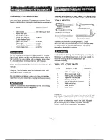
Page 6: ...g other accessories may be dangerous UNPACKING AND CHECKING CONTENTS TOOLS NEEDED Mediurn screwdriver 2 Phillips screwdriver I 1 1111tl 11 Straight edge Adjustable wrench Combination square Separate all parts from packing material Check each one with the illustration and the list of loose parts to make certain all items are accounted for before discarding any packing material If any parts are miss...

Page 7: ...d handle D Tool hangers Leg Pads Table insert 1 Dado lable insert 0 O o 0 0 0 0 i i i i i i i i i i i i i i i i i o o o o 0 o o h o II ol Mitre gauge Hex keys _ _ _ _ _ Bag of miscellaneous arts Ol o o o S ool 0 0 E C Leg set Hand wheels Blade wrenches li Owner s manual i O0 OO Page 7 ...

Page 8: ...e Table Blade Bevel Lock Knob Blade Bevel Scale Overload Blade Tilting Handwheel On Off Switch Tool Hanger Blade Kickback Pawls L I O Elevation Handwheel Mounting Holes Tool Hanger Steel Legs Wrenches Dado Insert Splitter l Splitter Bracket Page 8 ...

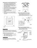
Page 9: ...rt into the leg flange hole and tighten using washer 9 and nut 10 Repeat for the three other legs 8 Attach bottom brackets 11 between each leg 9 Attach the hooks 12 to the frame as desired The hooks are used to hold the fence the blade wrenches and mitre gauge 10 Place leg set on a revel surface and tighten all nuts and bolts SAW TO LEG SET FIG B 1 Before mounting the rip and miler gauge to the sa...

Page 10: ...s drilled in the work surlace Failure to provide the sawdust fall4hrough and removal hole will allow sawdust to build up in the motor area which may result in a fire hazard or cause motor damage KEEPING THE AREA CLEAN FIG D 1 Saw dust and wood chips that fall from under the saw will accumulate on the floor 2 Make it a practice to pick up and discard this dust when you have completed cutting Always...

Page 11: ...g 4 CHANGING THE BLADE FIG H I J To avoid injury from an accidental start make sure the switch is in the OFF position and the plug is not connected to the power source outlet 1 Remove the table insert 1 by unscrewing the two screws 2 Be careful not to lose the rubber washer that is on the back screw beneath the table insert NOTE The back screw is longer than the front screw 3 1 Fig H 6 To tighten ...

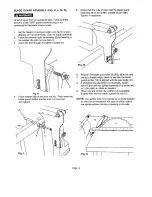
Page 12: ...plitter bracket 4 4 Fig K 3 1 Place washer 6 on the pivot rod 5 Then insert the blade guard splitter bracket onto the pivot red and tighten Fig L Fig 6 Position the blade guard arm 9 FIG N to the rear 7 Using a straight edge cheek to see that the blade guard splitter 10 is aligned with the saw blade 11 8 If straightening adjustment is necessary loosen bolt 1 and shift the splitter assembly 10 to t...

Page 13: ...he following 9 Move the handle 2 upward and turn the adjusting screw 5 clockwise until the rear clamp is snug Do not turn the adjusting screw 5 more than 1 4 turn at a lime 10 Over tightening the adjusting screw 5 will cause the fence to come out of alignment 90 8 6 7 5 2 m Fig P x___ x_ __ x__ 11 RIP FENCE ADJUSTMENT FIG P To avoid injury from an accidental start make sure the switch is in the OF...

Page 14: ...5 6 Turn the blade tilting handwheel until the blade is 90 to the table 7 Adjust the collar 5 so it contacts the bracket 3 when the blade is 90 to the table Tighten the two set screws 4 90 45 45 Stop 1 With the blade in the upright 900 position turn the blade tilting handwheel clockwise as far as it will go Remember to loosen the blade lock knob 2 Place the combination square on the table as shown...

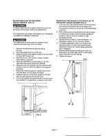
Page 15: ...t 1t2 inch above the table 8 Carefully slide the combination square to the rear until the ruler touches the marked tooth 9 If the ruler touches lhe marked tooth at the front and rear positions no adjustment is needed at this time ii j N I I I I Fig S ADJUSTING THE BLADE TO BE PARALLELTO THE MITER GAUGE GROOVE FIG T 1 If the front and rear measurements are not the same remove the combination square...

Page 16: ...ition Pr l lI ON OFF SWITCH FIG V The ON OFF switch has a removable key With the key removed from the switch unauthorized and hazardous use by children and others is minimized 1 To turn the saw ON insert key 1 into the slot in the switch 2 Move the switch upward to the ON position 2 To turn the saw OFR move the switch downward 3 To lock the switch in the OFF position grasp the end or yellow part o...

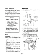
Page 17: ...r gauge Secure the rip fence to the table 2 Raise the blade so it is about 1 8 inch higher than the top of the workpiece 3 Place the workpiece flat on the table and against the fence Keep the workpiece about 1 inch away from the blade CAUTION The workpiece must have a straight edge against the fence and must not be warped twisted or bowed 4 Turn the saw ON and wait for the blade to come up to spee...

Page 18: ...e with the desired cut location Move the workpiece to one inch distance from the blade Keep both hands away from the blade and the path of the blade 4 Start the saw and wait for the blade to come up to full speed 5 Keep the workpiece against the face of the miter gauge and flat against the table Then slowly push the workpiece through the blade FIG X 6 Do not try to pull the workpiece back with the...

Page 19: ...e width 1 2 inch or less It will be necessary to remove the blade guard and splitter when using dado Use caution when dado is operating 6 Use only the correct number of round outside blades and inside chippers as shown in the dado set s instruction manual Blade or chipper must not exceed 1 2 7 Check saw to ensure that the dado will not strike the housing insert or motor when in operation For your ...

Page 20: ... rod 1 at thrust washer 5 Do not oil threads of screw rods 1 Screw rod 1 must be kept clean and free of saw dust gum pitch and other contaminants for smooth operation If excessive looseness is observed in any other part of the blade raising mechanism or tilting mechanism take the complete unit to a Sears Authorized Service Center MAINTENANCE BLADE RAISING AND TILTING MECHANISM After each five hour...

Page 21: ...e mounted backwards 3 Gum or pitch on blade 4 Incorrect blade for work being done 5 Gum or pitch on table causing erratic feed 1 Rip fence out of alignment 2 Splitter not aligned with blade 3 Feeding stock without rip fence 4 Splitter not in place 5 Dull blade 6 The operator letting go of material before it is past saw blade 7 Miter angle lock knob is not tight 1 Sawdust and dirt in raising and ti...

Page 22: ...on label 77 940077 Base 78 940078 Plate Key Part 79 940079 80 940080 81 940081 82 940082 83 940083 84 940084 85 940085 86 940086 87 940087 88 940088 89 940089 90 940090 91 940091 92 940092 93 940093 94 940094 95 940095 96 940096 97 9 10097 98 940098 99 940099 100 940100 101 940101 102 940102 103 940103 104 940104 105 940105 106 940106 107 940107 108 940108 109 940109 110 940110 111 940111 112 9401...

Page 23: ...TABLE SAW PARTS DIAGRAM e 5 12 13 43 44 45 49 58 _59 88 64 87 109 113 110 122 116 _ 136 121 120119 135 117 Page 23 145 148 147 146 139 138 133 132 131 t 52 143142_4 _ 140 _ 154 141 128 130 ...

Page 24: ... neck bolt Hex nut Bracket top long Bottom support bracket Spacer foot pad Hex hal bolt Hex nut Hex hal bolt Flat washer M8x1 25 16 M8x1 25 M8x1 5 20 M8X1 5 T 8 M8x1 25 30 e8x16 2 5 Key Part Description Size 11 940424 Hex nut M8x1 25 12 940425 Bracket _ top short 13 940426 Hex nut M6xl 0 14 940428 Hook 15 940429 Hex hd bolt M6xl 0 12 16 940434 Flat washer o10x20 2 Page 24 _ ...

Page 25: ...thickness less than width of material to be cut CAUTION _ Use only good I _ _ strong wood Cut off here to _ or plywood _ush 1 4 wood _ Cut off here to push 1 2 wood 1 2 Squares Notch to help J prevent hand from slipping O 3tional hanging hole O ...

Page 26: ...area Call 24 hoursa day 7 daysa week 1 800 488 1222 Forinformationon purchasinga Sears MaintenanceAgreementorto inquire about anexistingAgreement Call9 am 5 pm Monday Saturday 1 800 827 6655 The model number of your product is located on the name plate on the front of the table saw When requesting service or ordering parts always give the following information Product Type Part Number Model Number...

Reviews: