background image

Summary of Contents for 139.53225SRT

Page 1: ... aH safety rutes and operating instructions _fore first use of this product_ Fasten the manuat near the garage door after Complies with UL 325 _egulati_s effe_ve January 1 1_3 E Safety Precautions m Assembly m Installation H Adjustment Care and Maintenance Operation s Troubleshooting PaRs List OP Sears Roebuck and Co Hoffman Estates IL 60179 UoS A ...

Page 2: ...sensor _ 23 F_ten d_r bracket se ona_ d_O 24 Fasten dear bracket _e i_ dc_0 25 Conne_stdoor _q to oHe sedJonat d _O 26 _nn _ d_r a_ to troliey on_i_ d_aO 27 Adjustment sc_ion pages 28 30 Travel limit adjustments 28 Force adjustments 29 Test the _fe_ reve_ing sensor 3 0 Test U_e_fety _eve_e _ystem _O O_raflon _ etyinstm_ions 31 Care of your opene_ 31 M n_en_ce _hedule 3 I O_ra _on of your o_ner 32 ...

Page 3: ...become entangled and killed Remove all ropes connected to the door before installing and operating the opener Identify the type and height of your door and any speeia_ conditions that exist and any additional matedais that may be required by referring to the lists on page 4 or page 5 To avoid damage to the garage door and opener disable locks before installing and ope_ttng the opener U_ a w_d scre...

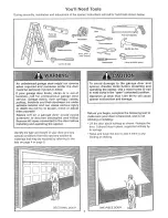
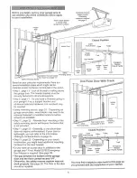
Page 4: ... will require hardware not Step 11 page 24 oDo you have a steel aluminum fiberglass or g _ss panel dood if so hodzontai and recital reinforcement is required Look at the garage door where it meets the fioor it must close o the floor sit the way across Other_wlse the safety reverse system may _ot work properlyo See page 30 Floor or d_r should be repaired oThe opener c_ be installed within 2 feet of...

Page 5: ...or mounting of the safety reversing sensor will require hardware that is not provided Step 11 page 25 _ Generally a one pie_ door does not require reinforcemenL tf your door is lightweight you _e refer to the information relating to section_ doors on page 24 Step 11 page 25 _Depending on your dooCs construction you might need additional mounting hardware for the door brackeL oDo you have an a_ess ...

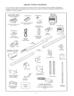
Page 6: ... carefu y check the packing matedaL PaAs may be stuck in Me foam_ Hardware for assembly and installation is shown on page 7 5_25 9 5_5 1 M_x_ieb 93225 Ugh_ed C4_ M_ _ S _24 or 4y Model 5_ e _y Compa_ R_o e C_tt_ _4ea_r Bt_ke_ S4sfe_yRevergr_ s_50 _ ua_ng Bta_ V_4_h Square H_ _ 2 Arm _ C_ _aim ar_8 C lm Safety Revers_g Sen_ Wth S_ 2 6 ...

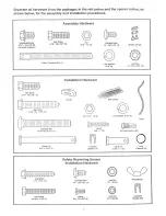
Page 7: ...r the assembly and installation procedures AssembLy Hardware T_o_ey ThCe_d_ Sh_ 1 _16 _ 4 I 4 _ 20 _ 7 16 _ 4 Installation Hardware H_ _d_ R_t Gte_ _1 _8 _ _o b_ _ 4 NL4 _ _8i6t Ro e Safety Reversing Sensor Installation Hardware Hex _ _w i _ 20 _ 11_ 2 Ca_ge _Rs Lo_ N_ _ i gN_ 2 _ 4 20 1_ 4 _ 4 _ 4 ...

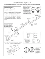
Page 8: ...ge bolts so the square bolt necks seat in the square holes in the T rai end sections and pass through the round holes in T_rait center section Assemble lock nuts ensure alignment and Ma_ sure _ n_ks are tig_en i_k nuts _ o_ratJon nef_ anddOr aa_n_ d_ re_r_lm END of T _a_l Pos_on _e_ble putiey bracket on _efront end of the T_raii as shown Fasten s_cure_yv_4th _e hardware Hardware Shown Actual S ze ...

Page 9: ...to protect the cover For coevenience pat a support under the came pui_ey brackeL Remove the 2 5 I6_18 1 2 _ washered _rews mounted in the top d the opener_ Atign the holes in the back seGion of the r ai_with the holes in the opener Fasten the rail with _e 2 washer_J screws previously remove Tighten securely Remember to use only these screwsf Any other screws wil cause serious damage to the opener ...

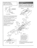
Page 10: ... Continue forward to the trolley thresd_ shaft Figure 3 Use the se_ md master _nk to connect the chain to the flat end of the shaft Check to make sure the chain is not twtsted Remove the screwdriver F_gure 3 Ma _er Unk n The Oit_a Master LJ_k Pr_r_ P_sh pins of r_3_stet link bar through _b_e k_p a_ hole in on_ end d t_liey Push _p over pins_nd into risk hoe Stag c_po_ spdng over _ep a_ into _yotch...

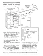
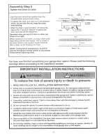
Page 11: ...erly balanced door may not reverse and could reautt in severe tnju_ or death Repairs to cables spring assemblies and other hardware must be made by a professional service person before installing opener_ 3 Disable aii iocks and remove all ropes connected to the garage door before ins tailing the opener _ Ropes connected to a garage doer can cause entanglement and death 4 _f possible install door o...

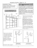
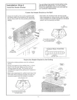
Page 12: ... wall _ _ above the de_ r _ Remember you can fasten the header bracket within 2 feet of the left or right of the door center only tf a torsion spring or center bearing p_ate is in the way or you can a_ach it to the ceiling refer to page 14 when clearance ts m_nimaL It may be mounted on the wall upstde down if necessary to gain appro imate_y 1 2 j If you need to install the header b_acket o _ a 2x4...

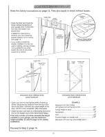
Page 13: ...pivot hardware Open your door to the highest _int of trave_ as shown Measure the distance from the top d the door to the floor Subtract t he actual height d the door Add 8_to the remainder See Example Close the door and draw an inte_ectJng horizontal line on the header w_l at the dete_ined height if the total number of inches exceeds the height available in your garage use the maximum height possi...

Page 14: ... and fasten the bracket securely to a stm_u_ suppo_ with the hardware provided W_ Hardware Shown Actua_ S_ze Fasten the Header Bracket to the Ceiling Extend the ve_icat guide ine onto the ceiling as shown Center the bracket on the ve_ica_ maP_ no more than 6 from the wall Make sure the arrew is pointing toward the wall The bracket can be mounted flush against the ceiling when clearance is minima_ ...

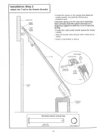
Page 15: ...rial as a If the door spring Is in the way you l need help Have someone hold the opener securely on a tem_ra_ suppoA to allow the T rail to clear the oPosition the _b_e puiley bracket against the header bracket Align the bracket holes and ioin with a clevis p_n as shewn hse_ a r_ngfastener to secure Hardware Shown Actual Size Clevis P_ O 15 ...

Page 16: ...he top panel hits the trolley when you raise the door puff down on the troltey release arm lo disconnect the inner and outer sections The trolley can remain disconnected until S_ep 12 is With the door fu y open and paratel to the floor measure the distance from the floor to the top of the door Using a stepladder as a sup_ raise the opener to the same distance as the d_r from the floor it will be a...

Page 17: ...ra support Cut both pieces of the hanging bracket to requ red DdH3 16 pilot h es in the structural supports Attach one end of each bracket to a support with 5 16 xl _ 7 8 _lag screws Fasten the opener to _he hanging brackets with 5 t 6_18x7 8 screws _ockwashers and nuts Check to make sure the Torai is centered over the door or in _inewith the header bracket if the bracket is not centered above the...

Page 18: ...il surface or becomes bose with time use _acks to secure the abe_ alongs de the wa_l control Page 32 explains bow to operate the opener using the lighted push bar or button as w as the L _k and L ight features on the Deiuxe Wail CorstroL Hardware Shown Actual Size 6AB x 8_tew Lghed Co_tsole Wail r on tel D0 Wa i Ar_chocs Children operath_g or p_ay_n9 w_th a garage door opener can injure themselves...

Page 19: ...Use the emergency release only to d_sengage the trolley and if possible only when the door ts etosed Garage doors are heavy If the door is open when the handle is pulled the door could close inadvertently if ft is not properly balanced Sedous injury may result to persons under the door Make sure the doorway ts clear of persons and obstructions before pulling handle when door is open Thread one end...

Page 20: ...e following procedure To prevent eiectrocufion remove power from the garage door opener and from the circuit you plan to use for the permanent connection To make a permanent oannection through the 718_diameter hole in the top of the opener according to I_l code Remove the opener cover screws and set the cover aside_ Remove the attached 3 prong cord Connect the black line wire to the screw on the b...

Page 21: ...he units can be installed on eider side of the garage door as long as the sun never shines directly into the receiving eye lens Lc_k at the label on the eonneGor end of each use to identiPy the sensors The brackets must be connected and fastened so that the sending and receiving eyes face each other as shown in Figure I If an obstruct on breaks the light beam while the garage door is c_osing_ the ...

Page 22: ...of the brackets for left and right stdes of the door_ Finger tighten the lock nuts o Use bracket mounting holes as a template to locate and drill 2 3 16 _diameter pilot holes on both sides d the g_age door 4 6 above the floor but not exceeding 6t See warning on AEach bracket assemblies with 1 4 xl 1 2 __ag _crews as shown in Figure 3 Adiust dght and le_ side bracket assemblies to the same distance...

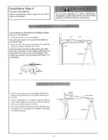
Page 23: ... offin the receiviog eye and the invisible light beam path is not obstru_ed _ alignment is required Loosen the receiving eye wing nut to alfow slight rotatiGq of unit Adjust sensor vertically newer hodzontaily until the green indicator light glows When indicator lights are glowing steadily in bo_h units tighten the wing nut in the receiving eye uniL Figure 6 1 If the sending eye indicator light do...

Page 24: ...e bracket on lhe face ot the door within the following limits A The top edge of the bracket 2 4 below the top edge of the door B The top edge d the bracket directly below any structural suppoM across the top of the door Mark and ddti ll 6 _eftand right fastening holes Secure the bracket as shown in Figure I if there is ve_ ticaI reinforcemenL if your installation doesn t require vertical reinforce...

Page 25: ...racket with hardware supplied_ _fthe door has no exposed framing drill 3 16 pilot holes nd fasten the bracket with 5 16_xl _1 2 lag screws not supplied to the top of the door The door bracket may be installed on the top edge of the door ff required for your installation Rder to the dotted line optional placement drawing Drill 3 16 pilot holes and substitute 5 16 x1_1_ lag screws not supplied to fa...

Page 26: ...ket in the same way as shown n_r Toffy F_gure 2 Bdng arm s6stJons together Find two pairs of holes that _ineup and join se_ions Select ho_es as far apart as possible to increase door arm rigidib o Hole Affgnment Alternative Figure 3 _ if holes in catered arm are above bores in straight arm disconnect straight am L Cut about 6 from the solid end Reconnect to trolley with cut end down as shown_ Brin...

Page 27: ...fer to the fully open trolley door am positio_ in the illustratiom If the arm does not extend far enough adjust the _imitfu_her One full turn equals 2 of Closed Door Adjustment D_rease DOWN limit Turn the DOWN Iim t adiustment screw cbckwise 5 Press _he Wa _Cont_ I push bar or button The troliey wiIt trave_ to the fully ctosed position Manually etose the door and iiff _e d_r arm to the troltey The...

Page 28: ...he door m_ght not reverse properly when required and could seriously injure or kill someone under it Test the safety reverse system following aH adjustments to the trave HInes See page 30 A_us_men_ f Le_ _ Pa_i How and When to Adjust the Limits f the door does not open completely but opens at least f ve feet hcrease up travel Turn the UP limit adjustment screw ciockwise One turn equals 2 of travel...

Page 29: ...WN close force Grasp the door bo_om when the door is about haffway through DOWN ctose travel The door should reverse Reversal halfway through down travel does not guarantee reversal on a two4nch obstruction See page 3 If the doer is hard to hold or doesnt reverse decrease the DOWN close force by turning the control counterc oekwise Make 10 degree turn adiustments unti_ the door reve_ esnormally Af...

Page 30: ... obstruction _fthe door steps on the obstruetion_ it isnot traveling far enough in the down direction o hcrease the DOWN limit by turning the DOWN Hmit adiustment screw countercJc_wise 1 4 turn Repeat the test On a sectional door make sure Ilmff adjustments do not force the door arm beyond a straight up and down positiom _ _e liasfmatlon on page 26 When the door reverses on the onednch t_ard remov...

Page 31: ...efore making any repairs or removing the covers s SAVE THESE INSTRUCTIONS Care of Your Opener Limit and force adjustment controls _e remote control Limit Controls Force Controls Ad ustmer_ L_bga Weather conditions may cause some minor changes in door operation requiring some re adjustments paAicularly dudng the first year of Pages 28 and 29 refer to the limit and force adiustments Only a screwdriv...

Page 32: ... intemJpted when _eopener is activated It will turn off autamati_ly after 4 112 minutes or provide constant light when the Light feature is activated Bulb size is 75 wa_s maximum Bme_ger_ Re_ HarcJ_ Manual d_sconnect The toeko_ feature prevents the troliey from reconnecting aatomat caIty_ Pull the down and back toward the opener The door can then be raised and lowered manually as often as necessar...

Page 33: ...e and cause serious injury or death Do not allow children tO operate the wat push button s or remote A moving garage doer could injure or kill someone under it_ Activate the opener only when you can see the door c ear y it is free of obstructions and is properly adjusted Figure 1 S ngle Function M R_ 3 Fan ion Remote Control Remote_Control _o to _te O_er To Add A Remote Control 1 Se e_ a remote co...

Page 34: ...h the remote control code 5 Repeat the receiver programming procedure with aft remote controls _ee remote control 1 Check the battery test light if the light is d m replace the bakery 2_ Change the Iocation of the remote centre r_yourcar_ 3 Check to be sure the antenna on the side or back panel of opener extends fully downward 4 Some instailations may have sho_er range due to a meta_ door toil bac...

Page 35: ...gs are broken C_ose the d_r art_ u_ the maximum force is emergen televise to di_ onne_ the trolley Open and cio_ _e d_r m_ _ual y A property beJan_d d_r will stay in _y p int of _ave_ while _ing sup_d6 l entireb by its spdr_s If it door d_s not_disconnect _e o_ner _nd c_ I a professional ga_ e de_r _eviceman Do not increase the force to o_te t 5e o_nero The opener motor 1 The garage door spdngs ar...

Page 36: ...0 83A4 4 t A3473 41B2616 4 A3594 Master link kR Compiete t_ei ey assembly Torai_ center section Lrai _ end sect on each Chain _d cabte Cabie pulley bracket assembly NOT BROWN Rai assembly hardware kit in _udes hardware i_lustrat_ on page 7 i78B35 178B_ 12B350 12_84 12_83 12 _85 Remote control visor c ip Emergency _ope handle assy 2_onductor bell wire _ white white red Door bracket Header bracket w...

Page 37: ...apacitor 1 2 hp Capacitor 3 hp Capac tor 1 4 h Terminal b _k w screws 12 41A3 474 1 41A3474_2 41A_74o5 13 41A2818 14 4103452 15 41C4898A 16 41C4246 7 41A2826 18 414JZ822A 9 41A4315 7C Ung_e_31 replacement motor and bracket assemNy Complete with Motoc worm bracket bearing assembly RPM sensor Cover 1 2 h p Cover _ 1 3 h po Cover o 1 4 h p HeI_ gear and retainer w grease RPMsensor assembly Wire hames...

Page 38: ...r in garage with iow headroom clearance 53759 53773 53774 53_5 53779 3 Function Compact Remote Control With key dr_g Velcro faster in9 W_re4n Light Contro_ Controls intedor or extedor Iights Wires into the electrica_ box like a dimmer switch_ Pfugqn Light Control Controls interior Iights Piugs into a wall receptacle Mu_ti Function Key_ess EntPj Enables homeowner to operate garage door opener from ...

Page 39: ...prc_edures 28 Problems that might requk_ limit adiustments 34 35 Safety warnings 28 31 Manual Emergency Release Rope Handle Lc skout feature 32 Manual di_onnect 32 Safety warnings 1I 19 31 32 Wall contro_ connections 18 Safety reversing sensor connections 23 O_ tdoor key switch a_essoPj connections 18 Sprocket noise 11 Vibration noise isolator kit 34 Receiver and Remote Control Programming the rec...

Page 40: ...lacement pa_s you need Cati 7 am 7 pm 7 days a week 1 oaooo366oPART For mhome maior brand repair service Cali 24 hours a day 7 days a week t _800 4_REPAIR For the location of a Sears Repair Service Center in your area Caii 24 hours a day 7 days a week t o8OOo488 1222 For information on purchasing a Sears Maintenance Agreement or to inquire about an existing Agreement CaR9 am 5 pm Monday Saturday S...

Reviews: