background image

Summary of Contents for 139.53525SRT

Page 1: ...ing instructions before first use of this product Fasten the manual near the garage door after installation Complies with UL 325 11 ii N_ regulations effective January 1993 I RRFTSMRNo 1 2 HP GARAGE DOOR OPENER Safety Precautions Assembly Installation Adjustment Care and Maintenance Operation Troubleshooting Parts List Sears Roebuck and Co Hoffman Estates IL 60179 U S A ...

Page 2: ...to trolley one piece door 27 Adjustment section pages 28 30 Travel limit adjustments 28 Force adjustments 29 Test the safety reversing sensor 30 Test the safety reverse system 30 Operation safety instructions 31 Care of your opener 31 Maintenance schedule 31 Operation of your opener 32 Receiver and remote control programming 33 Having a problem 34 35 Repair parts rail assembly 36 Repair parts inst...

Page 3: ...on a garage door could cause someone to become entangled and killed Remove all ropes connected to the door before installing and operating the opener Identify the type and height of your door and any special conditions that exist and any additional materials that may be required by referring to the lists on page 4 or page 5 To avoid damage to the garage door and opener disable locks before install...

Page 4: ...loor mounting of the safety reversing sensor will require hardware not provided Step 11 page 24 Do you have a steel aluminum fiberglass or glass panel door If so horizontal and vertical reinforcement is required Look at the garage door where it meets the floor It must close on the floor all the way across Otherwise the safety reverse system may not work properly See page 30 Floor or door should be...

Page 5: ...he safety reversing sensor will require hardware that is not provided Step 11 page 25 Generally a one piece door does not require reinforcement If your door is lightweight you can refer to the information relating to sectional doors on page 24 Step 11 page 25 Depending on your door s construction you might need additional mounting hardware for the door bracket Do you have an access door in additio...

Page 6: ...nly Multi Function Single Function Remote ControI Keylees Entry with Visor Drip 1 Lighted ConeoIe Wall ControI Models 53225 53325 53628 53629 _ _ Pulley Bracket Lighted Push Button Wall Controt _ _ 2 Conductor and Hardware _ Be Wire _ _ _ White White Red y _ J T Ro End sections Door Bracket Plate Modet 53824 only Deluxe Wall Control Door Bracket Sprocket Cover Safety Reversing Sensor Mounting Brac...

Page 7: ...ck Washer 5 16 4 Lock Nut 1 4 20 x 7 16 4 1111111111 Hex Screw 5 16 18 x 7 8 4 5 16 18 x 1 7 8 4 Installation Hardware Handte Nut 5 16 18 6 Rail Grease Carriage Bott 5 16 18 x 2 1 2 2 Clevis Pin 5 16 x 2 3 4 1 o Screw 6AB x 1 2 Lock Washer 5 16 6 Dry Wail Anchors 2 Insulated CIevis Pin Staples 10 5 16 x 1 2 Rope O Ring Fastener 3 Hex Screw 1 4 20 x 1 1 2 2 Safety Reversing Sensor Installation Hard...

Page 8: ...ee right and wrong views Improper assembly can cause jerky trolley operation noise and or Right Wrong nuisance door reversals T RAIL BACK TO OPENER Brace 1 4 Lock Nut T rait End Section if T rail is not assembled EXACTLY as shown trolley will not travel smoothly along length of rail or it will hit against the nuts T rail End Section Brace Cable pulley bracket attaches to FRONT END of T rait Square...

Page 9: ... to the Opener Place the opener on packing material to protect the cover For convenience put a support under the cable pulley bracket Remove the 2 5 16 18x1 2 washered screws mounted in the top of the opener Align the holes in the back section of the T rail with the holes in the opener Fasten the rail with the 2 washered screws previously removed Tighten securely Remember to use only these screws ...

Page 10: ...tinue forward to the trolley threaded shaft Figure 3 Use the second master link to connect the chain to the flat end of the shaft Check to make sure the chain is not twisted Remove the screwdriver Master Link CIip On Spring i i i i Mast Link Cap _ Cable Loop _ Master Link Clip On Spring _ _ i Master Link Cap Flat End of TrolIey Threaded Shaft Figure 3 Chain T rail Pin Notch Install Chain and Cabte...

Page 11: ...l only on a properly balanced and lubricated garage door An improperly balanced door may not reverse and could result in severe injury or death Repairs to cables spring assemblies and other hardware must be made by a professional service person before installing opener 3 Disable all locks and remove all ropes connected to the garage door before installing the opener Ropes connected to a garage doo...

Page 12: ...to the header wall above the door Remember you can fasten the header bracket within 2 feet of the left or right of the door center only if a torsion spring or center bearing plate is in the way or you can attach it to the ceiling refer to page 14 when clearance is minimal It may be mounted on the wall upside down if necessary to gain approximately 1 2 If you need to install the header bracket on a...

Page 13: ..._l I j Highest Point One piece door without track jamb hardware One piece door without track pivot hardware Open your door to the highest point of travel as shown Measure the distance from the top of the door to the floor Subtract the actual height of the door Add 8 to the remainder See Example Close the door and draw an intersecting horizontal line on the header wall at the determined height If t...

Page 14: ...oles 2x4 Structural Support Highest Point of Travel of Garage Door Door Spring Door Vertical Center Line The nail hole is for positioning only You must use lag screws to mount the header bracket Optional Wall Mounting Holes Hardware Shown Actual Size 5 16 18xl 7 8 Fasten the Header Bracket to the Ceiling Extend the vertical guideline onto the ceiling as shown Center the bracket on the vertical mar...

Page 15: ... you ll need help Have someone hold the opener securely on a temporary support to allow the T rail to clear the spring Position the cable pulley bracket against the header bracket Align the bracket holes and join with a clevis pin as shown Insert a ring fastener to secure Ring Fastener Header Bracket 0 i C_ I Ctevis Pin 5 16 x2 3 4 Cable Pulley Bracket Door Temporary Support Hardware Shown Actual ...

Page 16: ... trolley when you raise the door pull down on the trolley release arm to disconnect the inner and outer sections The trolley can remain disconnected until Step 12 is completed Door 2x4 Laid Fiat Tro y With the door fully open and parallel to the floor measure the distance from the floor to the top of the door Using a stepladder as a support raise the opener to the same distance as the door from th...

Page 17: ...engths Drill 3 18 pilot holes in the structural supports Attach one end of each bracket to a support with 5 16 xl 7 8 lag screws Fasten the opener to the hanging brackets with 5 18 18x7 8 screws lock washers and nuts Check to make sure the T rail is centered over the door or in line with the header bracket if the bracket is not centered above the door Remove the 2x4 Operate the door manually If th...

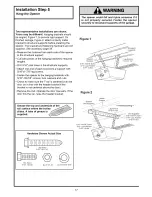
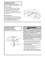
Page 18: ...re to your garage wall surface or becomes loose with time use tacks to secure the label alongside the Wall Control Children operating or playing with a garage door opener can injure themselves or others The garage door could close and cause serious injury or death Install the Wall Control or any additional push buttons out of the reach of children and away from all moving parts of the door and doo...

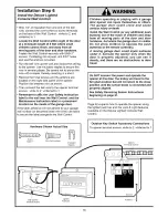
Page 19: ... Knot _ Do not use the red handle to pull the door open or closed The rope knot could become untied and you could fall Use the emergency release only to disengage the trolley and if possible only when the door is closed Garage doors are heavy If the door is open when the handle is pulled the door could close inadvertently if it is not properly balanced Serious injury may result to persons under th...

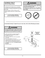
Page 20: ...e adapter or change the plug in any way to make it fit your outlet Right Wrong If permanent wiring is required by your local code refer to the following procedure To make a permanent connection through the 7 8 diameter hole in the top of the opener according to local code Remove the opener cover screws and set the cover aside Remove the attached 3 prong cord Connect the black line wire to the scre...

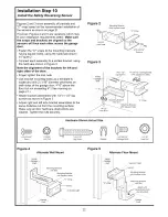
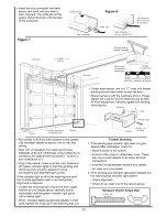
Page 21: ...er side of the garage door as long as the sun never shines directly into the receiving eye lens Look at the label on the connector end of each case to identify the sensors The brackets must be connected and fastened so that the sending and receiving eyes face each other as shown in Figure 1 If an obstruction breaks the light beam while the garage door is closing the door will stop and reverse to f...

Page 22: ...exceeding 6 See warning on page 21 Attach bracket assemblies with 1 4 x1 1 2 lag screws as shown in Figure 3 Adjust right and left side bracket assemblies to the same distance out from the mounting surface Make sure all door hardware obstructions are cleared Tighten the nuts securely Figure 2 Mounting Bracket With Square Holes C Wrap 10 32 Lock Nuts 10 32x3 8 Screws Figure 3 Inside Garage Wa 1 4x1...

Page 23: ...wires sufficiently to connect to the opener terminal screws white to 2 and white black to 3 Plug in the opener Make sure the Lock Feature is off Green indicator lights in both the sending and receiving eyes will glow steadily if wiring connections and alignment are correct If the indicator light is offin the receiving eye and the invisible light beam path is not obstructed alignment is required Lo...

Page 24: ...aeet etc Figure 1 Door Bracket Location Carriage BoIt 5 16 18x2 1 2 Door Bracket Lock Washer 5 16 j_ Nut Vertical _ 5 16 18 Guideline Figure 2 Inside Ed of Door or Reinforcement Board Door Center the door bracket on the previously marked vertical guideline used for the header bracket installation Position the bracket on the face of the door within the following limits A The top edge of the bracket...

Page 25: ...fasten door bracket _ Center the bracket on the top of the door in line with the header bracket as shown Mark holes Drill 5 16 pilot holes and fasten the door bracket with hardware supplied If the door has no exposed framing drill 3 16 pilot holes and fasten the bracket with 5 16 x1 1 2 lag screws not supplied to the top of the door The door bracket may be installed on the top edge of the door if ...

Page 26: ...gure 2 Bring arm sections together Find two pairs of holes that line up and join sections Select holes as far apart as possible to increase door arm rigidity Lock II Washers I_ R pe 5 16 _ _ t _ Z Jk EmergenNuts _ t _f_ ReleasCY _ _5 lS c 18x7 85 16 18 _ _L Handle Figure 2 Hole Alignment Alternative Figure 3 If holes in curved arm are above holes in straight arm disconnect straight arm Cut about 6...

Page 27: ... The arm should touch the trolley just in back of the door arm connector hole Refer to the fully open trolley door arm positions in the illustration If the arm does not extend far enough adjust the limit further One full turn equals 2 of trolley travel Closed Door Adjustment Decrease DOWN limit Turn the DOWN limit adjustment screw clockwise 5 complete turns Press the Wall Control push bar The trol...

Page 28: ...ration of the opener during adjustment procedures may cause the motor to overheat and shut off Simply wait 15 minutes and try again Read the procedures carefully before proceeding to Adjustment Step 2 Use a screwdriver to make limit adjustments How and When to Adjust the Limits If the door does not open completely but opens at leastfive feet Increase up travel Turn the UP limit adjustment screw cl...

Page 29: ...Panel How and When to Adjust the Forces Test the DOWN close force Grasp the door bottom when the door is about halfway through DOWN close travel The door should reverse Reversal halfway through down travel does not guarantee reversal on a two inch obstruction See page 30 If the door is hard to hold or doesn t reverse decrease the DOWN close force by turning the control counterclockwise Make 10 deg...

Page 30: ...tered under the garage door Operate the door in the down direction The door must reverse on striking the obstruction Adjustment If the door stops on the obstruction it is not traveling far enough in the down direction Increase the DOWN limit by turning the DOWN limit adjustment screw counterclockwise 1 4 turn Repeat the test On a sectional door make sure limit adjustments do not force the door arm...

Page 31: ... THESE INSTRUCTIONS Care of Your Opener Limit and force adjustment controls Limit Controls Force Controls Adjustment Label Adjustment Labet Located on the teft side panel Located on the right side panel Weather conditions may cause some minor changes in door operation requiring some re adjustments particularly during the first year of operation Pages 28 and 29 refer to the limit and force adjustme...

Page 32: ...release rope and handle only when the door is fully closed ease Arm Emergency ReIease Handte Pull Down Manual disconnect position To open the door manually The door should be fully closed if possible Pull down on the red emergency release handle and lift the door manually To reconnect the door to the opener press the Wall Control push bar The lockout feature __ prevents the trolley from I 1F_ _7 T...

Page 33: ... Button Your SRT garage door opener will operate with as many as four SRT portable remote controls and one Multi Function Keyless Entry To Add A Remote Control 1 Select a remote control push button to operate the receiver 2 Press and hold the selected remote control push button Figure 1 3 Then press and release the SRT button on the right side panel of the opener in Figure 2 The opener light will ...

Page 34: ...remote control code 5 Repeat the receiver programming procedure with all remote controls The remote control has short range Opener noise is disturbing in living quarters of home The garage door opens and closes by itself 1 Check the battery test light If the light is dim replace the battery 2 Change the location of the remote control in your car 3 Check to be sure the antenna on the side or back p...

Page 35: ...feature on Turn it off The door may be out of balance or the springs are broken Close the door and use the emergency release to disconnect the trolley Open and close the door manually A properly balanced door will stay in any point of travel while being supported entirely by its springs If it does not disconnect the opener and call a professional garage door serviceman Do not increase the force to...

Page 36: ... 29C128 9 41A2828 10 217A238 11 12B380 12 12B374 13 41A4353 14 41A4373A 15 178B35 16 178B34 17 12B350 18 12B484 19 12B483 20 12B485 41A3535 41A4116 114A1903 3 function remote control housing screw only 3 function compact remote control housing screw only 12V battery Remote control visor clip Emergency rope handle assy 2 conductor bell wire white white red Door bracket plate Door bracket Header bra...

Page 37: ...ire harness assembly w plug Receiver logic board assembly Complete with Logic board End panel w all labels End panel w all labels Light socket KEY NO 9 10 11 12 13 14 15 16 17 18 19 20 PART NO 108D46 30B363 12A373 41A3150 41D3058 41A3474 41A2818 41D3452 41C4398A 41A2826 41A2822A 41A4352 41A2825 DESCRIPTION Lens Capacitor 1 2HP Capacitor bracket Terminal block w screws Universal replacement motor b...

Page 38: ...rollers on door to reduce height of door travel For use when installing opener in garage with low headroom clearance 53773 H ii 53774 53776 53779 3 Function Compact Remote Control With key ring Velcro fastening strip Wire In Light Control Controls interior or exterior lights Wires into the electrical box like a dimmer switch Plug In Light Control Controls interior lights Plugs into a wall receptac...

Page 39: ...nts 34 35 Safety warnings 28 31 Manual Emergency Release Rope Handle Lockout feature 32 Manual disconnect 32 Safety warnings 11 19 31 32 Opener Terminals Wall control connections 18 Safety reversing sensor connections 23 Outdoor key switch accessory connections 18 Operational Noise Sprocket noise 11 Vibration noise isolator kit 34 Receiver and Remote Control Programming the receiver 33 Erasing all...

Page 40: ... parts for any defective parts free of charge You pay for labor LIMITED WARRANTY ON 1 2 HP AND 1 3 HP MOTORS FOR CRAFTSMAN OPENERS I 2HP MOTOR After 1 year and through 5 years Sears will furnish replacement parts for any defective parts in motor free of charge You pay for labor I 3HP MOTOR After 1 year and through 3 years Sears will furnish replacement parts for any defective parts in motor free o...

Reviews: