background image

4

Planificación

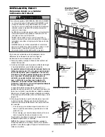
Identifique la altura y el tipo de su puerta de cochera.
Revise el área de su cochera y observe si alguna de
las siguientes instalaciones corresponden a la suya.
A veces se requieren materiales adicionales, así que tal
vez sea conveniente tener esta hoja y las ilustraciones
correspondientes a la mano cuando inicie la instalación de
su abridor.

Dependiendo de sus necesidades individuales, es posible
que en algunos casos vaya a necesitar materiales o
herramientas que no se incluyen con este producto.

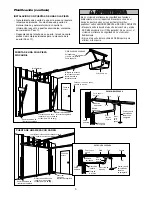
• Instalación Paso 1 – Mire la pared o el techo encima de

la puerta de garaje. El paréntesis de encabezamiento
debe ser abrochado seguramente a apoyos
estructurales. 

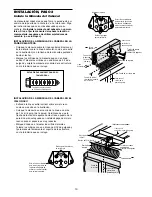
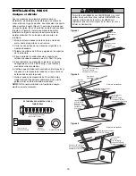
• Instalación Paso 5 – Si el plafón o cielo raso de su

cochera tiene acabado, es posible que necesite una
ménsula de soporte y/o más pernos y tornillería para la
instalación.

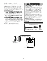
• Instalación Paso 10 – Dependiendo del tipo de

construcción de su cochera, es posible que necesite
ménsulas de extensión o bloques de madera para
instalar los sensores.

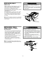
• Instalación Paso 10 – El montaje en el piso del sensor

que activa el sistema de retroceso de seguridad podría
requerir piezas que no se incluyen.

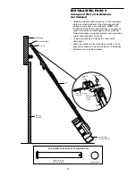
• ¿Hay otra puerta que dé acceso a la cochera? Si no es

así, será necesario contar con el sistema de llave de
emergencia Modelo 53702 Vea la página de Accesorios.

• Observe el punto donde la puerta hace contacto con el

piso. El espacio entre la base de la puerta y el piso no
debe exceder 6 mm (1/4 de pulgada). Si no es así, se
corre el riesgo de que el sistema de retroceso de
emergencia no funcione correctamente. Vea Ajustes,
Paso 3. Será necesario reparar ya sea el piso o la
puerta.

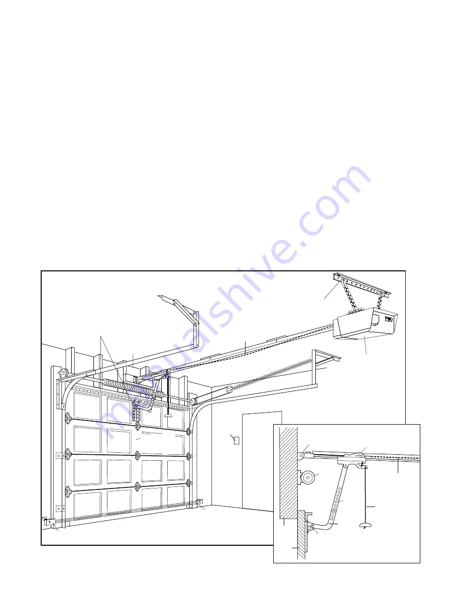
INSTALACIÓN CON UNA PUERTA SECCIONAL

• Si tiene una puerta de acero, aluminio, fibra de vidrio, o

con paneles de vidrio, necesitará refuerzos verticales y
horizontales en la puerta. (Instalación, Paso 11).

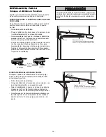
• El abridor se debe instalar arriba del centro de la puerta,

pero si existe algún resorte de tensión o placa de apoyo
en el paso de la ménsula del cabezal, se puede instalar
hasta a 1.2 m (4 pies) a la derecha o a la izquierda del
centro de la puerta. Vea Instalación, Pasos 1 al 11.

• Si su puerta es de más de 2.1 m (7 pies) de altura, vea

Extensiones de riel en la sección de Accesorios.

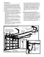
El espacio entre la base de
la puerta y el piso no debe de
exceder 6 mm (1/4 de pulg.).

Resorte de extensión

Resorte de torsión

Sensor del sistema
de retroceso de seguridad

Los refuerzos verticales y horizontales son 
necesarios para las puertas de cochera de
materiales más livianos (fibra de vidrio, acero,
aluminio, o puertas con paneles de vidrio).
Vea la página 23, donde encontrará más detalles.

Se requiere ménsula de
soporte y tornillos o
sujetadores. Vea la página 16.

Pared delantera

Puerta de
acceso

Unidad del motor

Unidad de
control de
la puerta,
instalada
en la pared

Sensor del sistema
de retroceso de seguridad

La holgura en la tensión 
de la cadena es normal 
cuando la puerta se 
encuentra cerrada


Línea central
vertical dela 
puerta de garaje

CIELO RASO CON ACABADO

INSTALACIÓN CON UNA PUERTA SECCIONAL

Cadena

Ménsula
del cabezal

Trole

Brazo 
recto de
la puerta

Cuerda y manija
del sistema de
liberación
de emergencia

Ménsula
de la
puerta

Puerta
de la
cochera

Brazo 
curvo de
la puerta

Resorte
de la
puerta de
cochera

Pared
delantera

EN POSICIÓN CERRADA

Summary of Contents for 139.5364812

Page 1: ...d follow all safety rules and operating instructions before first use of this product Fasten the manual near the garage door after installation Periodic checks of the opener are required to ensure safe operation Leer y seguir todas las reglas de seguridad y las instrucciones de operación antes de usar este producto por primera vez Guardar este manual cerca de la puerta de la cochera Se deben reali...

Page 2: ...e door opener 32 Having a problem 33 Diagnostic chart 34 Programming 35 36 To add or reprogram a hand held remote control 35 To erase all codes 35 Multi function remotes 35 To add reprogram or change a Keyless Entry PIN 36 Repair Parts 37 38 Rail assembly parts 37 Installation parts 37 Motor unit assembly parts 38 Accessories 39 Warranty 39 Repair Parts and Service Back Cover TABLE OF CONTENTS Whe...

Page 3: ...garage door Before you begin Disable locks Remove any ropes connected to garage door Complete the following test to make sure your garage door is balanced and is not sticking or binding 1 Lift the door about halfway as shown Release the door If balanced it should stay in place supported entirely by its springs 2 Raise and lower the door to see if there is any binding or sticking If your door binds...

Page 4: ...nished ceiling in your garage If so a support bracket and additional fastening hardware may be required Installation Step 10 Depending upon garage construction extension brackets or wood blocks may be needed to install sensors Installation Step 10 Alternate floor mounting of the safety reversing sensor will require hardware not provided Trolley Header Wall Garage Door Header Bracket Straight Door ...

Page 5: ...eversing Sensor Gap between floor and bottom of door must not exceed 1 4 6 mm Wall mounted Door Control Motor Unit ONE PIECE DOOR WITHOUT TRACK CLOSED POSITION Cable Pulley Bracket Header Bracket Trolley Straight Door Arm Emergency Release Rope Handle Door Bracket Curved Door Arm Header Wall Cable Rail Garage Door Without a properly working safety reversal system persons particularly small childre...

Page 6: ...sor Mounting Bracket With Slot 2 Safety Reversing Sensor Mounting Bracket With Square Holes 2 2 Safety Reversing Sensors 1 Sending Eye and 1 Receiving Eye with 2 Conductor White White Black Bell Wire attached Your garage door opener is packaged in two cartons which contain the motor unit and all parts illustrated below Accessories will depend on the model purchased If anything is missing carefully...

Page 7: ... in motor unit Carriage Bolts 1 4 20x1 2 4 Hex Bolt 5 16 18x7 8 3 Master Link 2 Ring Fastener 3 Threaded Trolley Shaft 1 Lock Washer 5 16 6 Lag Screw 5 16 18x1 7 8 2 Wing Nut 1 4x20 2 Hex Bolt 5 16 18x7 8 4 Carriage Bolts 1 4 20x1 2 4 Lag Screw 5 16 9x1 5 8 2 Clevis Pin 5 16 x1 1 4 1 Carriage Bolt 5 16 18x2 1 2 2 Lock Nut 1 4 20 4 Hex Bolt 1 4 20x1 1 2 2 Screw 10 32x3 8 4 Lock Nut 10x32 4 Insulate...

Page 8: ...ure alignment and tighten NOTE If rail is not assembled exactly as shown trolley will not travel smoothly along length of rail or it will hit against nuts 4 Position the cable pulley bracket on the front end of the rail as shown Fasten securely with the hardware shown NOTE When tightening the bolts be sure to keep bracket parallel to the rail Otherwise the rail may bow when the opener is operated ...

Page 9: ...ecurely with a 5 16 lock washer and nut NOTE This bolt prevents trolley over travel Keep a 2 5 mm minimum between the trolley and this bolt when adjusting travel limits see page 27 Washered Screw 5 16 18x1 2 Rail Back Section Cover Protection Bolt Hole Nut 5 16 18 Hex Bolt 5 16 18x7 8 Lock Washer 5 16 USE ONLY THIS TYPE AND SIZE SCREW To avoid SERIOUS damage to opener ONLY use bolts fasteners moun...

Page 10: ...onnect the chain to the flat end of the shaft Figure 1 Check to make sure the chain is not twisted 5 Remove the screwdriver ATTACHING THE SPROCKET COVER Insert the back tab in the slot on the back of the mounting plate Squeeze the cover slightly and insert the front tab Figure 3 To avoid possible SERIOUS INJURY to fingers from moving garage door opener ALWAYS keep hand clear of sprocket while oper...

Page 11: ...er only on properly balanced and lubricated garage door An improperly balanced door may not reverse when required and could result in SEVERE INJURY or DEATH 3 All repairs to cables spring assemblies and other hardware MUST be made by a trained door systems technician BEFORE installing opener 4 Disable all locks and remove all ropes connected to garage door BEFORE installing opener to avoid entangl...

Page 12: ... of the door NOTE If the total number of inches exceeds the height available in your garage use the maximum height possible or refer to page 13 for ceiling installation To prevent possible SERIOUS INJURY or DEATH Header bracket MUST be RIGIDLY fastened to structural support on header wall or ceiling otherwise garage door might not reverse when required DO NOT install header bracket over drywall Co...

Page 13: ...P CEILING MOUNT ONLY Wall Mounting Holes Optional Wall Mounting Holes The nail hole is for positioning only You must use lag screws to mount the header bracket UP CEILING MOUNT ONLY Door Spring Header Bracket 2x4 Structural Support Horizontal Line Vertical Centerline of Garage Door Vertical Centerline of Garage Door UP CEILING MOUNT ONLY Ceiling Mounting Holes The nail hole is for positioning only...

Page 14: ...ION STEP 3 Attach the Rail to the Header Bracket Position the opener on the garage floor below the header bracket Use packing material as a protective base NOTE If the door spring is in the way you ll need help Have someone hold the opener securely on a temporary support to allow the rail to clear the spring Position the rail bracket against the header bracket Align the bracket holes and join with...

Page 15: ...for setting an ideal door to rail distance Remove foam packaging Raise the opener onto a stepladder You will need help at this point if the ladder is not tall enough Open the door all the way and place a 2x4 laid flat on the top section beneath the rail If the top section or panel hits the trolley when you raise the door pull down on the trolley release arm to disconnect inner and outer sections S...

Page 16: ...with the header bracket if the bracket is not centered above the door 7 Remove the 2x4 Operate the door manually If the door hits the rail raise the header bracket NOTE DO NOT connect power to opener at this time To avoid possible SERIOUS INJURY from a falling garage door opener fasten it SECURELY to structural supports of the garage Concrete anchors MUST be used if installing any brackets into ma...

Page 17: ...ed and there are no obstructions to door travel ALWAYS keep garage door in sight until completely closed NEVER permit anyone to cross path of closing garage door WARNING CAUTION WARNING WARNING INSTALLATION STEP 6 Install the Door Control Locate door control within sight of door at a minimum height of 5 feet 1 5 m where small children cannot reach away from moving parts of door and door hardware I...

Page 18: ...hread the other end of the rope through the hole in the release arm of the outer trolley Adjust rope length so the handle is 6 feet 1 8 m above the floor Secure with an overhand knot NOTE If it is necessary to cut the rope heat seal the cut end with a match or lighter to prevent unraveling To prevent possible SERIOUS INJURY or DEATH from a falling garage door If possible use emergency release hand...

Page 19: ...the black line wire to the screw on the brass terminal the white neutral wire to the screw on the silver terminal and the ground wire to the green ground screw The opener must be grounded Reinstall the cover To avoid installation difficulties do not run the opener at this time RIGHT WRONG To prevent possible SERIOUS INJURY or DEATH from electrocution or fire Be sure power is not connected to the o...

Page 20: ...or Either can be installed on the left or right of the door as long as the sun never shines directly into the receiving eye lens The mounting brackets are designed to clip onto the track of sectional garage doors without additional hardware If it is necessary to mount the units on the wall the brackets must be securely fastened to a solid surface such as the wall framing Extension brackets see acc...

Page 21: ...arage door tracks themselves Figure 4 and 5 are variations which may fit your installation requirements better Make sure the wraps and brackets are aligned so the sensors will face each other across the garage door Garage Wall or Door Track Installation 1 Fasten the C wraps to the mounting brackets having square holes using th hardware shown in Figure 1 Garage Wall Installation 2 Connect each asse...

Page 22: ...d See page 20 Figure 7 MOUNTING AND WIRING THE SAFETY SENSORS Slide a 1 4 20x1 2 carriage bolt head into the slot on each sensor Use wing nuts to fasten sensors to brackets with lenses pointing toward each other across the door Be sure the lens is not obstructed by a bracket extension Figure 6 Finger tighten the wing nuts Run the wires from both sensors to the opener Use insulated staples to secur...

Page 23: ...r bracket on the previously marked vertical centerline used for the header bracket installation Note correct UP placement as stamped inside the bracket Figure 2 Position the bracket on the face of the door within the following limits A The top edge of the bracket 2 4 5 10 cm below the top edge of the door B The top edge of the bracket directly below any structural support across the top of the doo...

Page 24: ...gs and reinforcement instructions on the previous page They apply to one piece doors also Center the door bracket on the top of the door in line with the header bracket as shown Mark either the left and right or the top and bottom holes Drill 5 16 pilot holes and fasten the bracket with hardware supplied If the door has no exposed framing drill 3 16 pilot holes and fasten the bracket with 5 16 x1 ...

Page 25: ... far apart as possible to increase door arm rigidity Figure 3 Hole alignment alternative If holes in curved arm are above holes in straight arm disconnect straight arm Cut about 6 15 cm from the solid end Reconnect to trolley with cut end down as shown Bring arm sections together Find two pairs of holes that line up and join with bolts lock washers and nuts Proceed to Adjustment Step 1 page 27 Tro...

Page 26: ...Washers 5 16 Ring Fastener Straight Arm Bolts 5 16 18x7 8 Door Bracket Clevis Pin 5 16 x1 1 4 Curved Door Arm Press the Door Control push button The trolley will travel to the fully closed position Manually close the door and lift the door arm to the trolley The arm should touch the trolley just ahead of the door arm connector hole Refer to the fully closed trolley door arm positions in the illust...

Page 27: ...in Adjustment Step 2 If the door does not close completely Increase down travel Turn the down limit adjustment screw counterclockwise One turn equals 2 5 cm of travel If door still won t close completely and the trolley bumps into the pulley bracket page 4 try lengthening the door arm page 25 and decreasing the down limit If the opener reverses in fully closed position Decrease down travel Turn th...

Page 28: ...Make small adjustments until the door completes a close cycle After each adjustment run the opener through a complete travel cycle Do not increase the force beyond the minimum amount required to close the door 2 Test the UP open force Grasp the door bottom when the door is about halfway through UP open travel The door should stop If the door is hard to hold or doesn t stop DECREASE UP open force b...

Page 29: ... the 1 1 2 3 8 cm board remove the obstruction and run the opener through 3 or 4 complete travel cycles to test adjustment IMPORTANT SAFETY CHECK Repeat Adjustment Steps 1 2 and 3 after Each adjustment of door arm length limits or force controls Any repair to or adjustment of the garage door including springs and hardware Any repair to or buckling of the garage floor Any repair to or adjustment of...

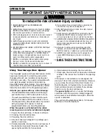
Page 30: ...reverse The opener lights will turn on under the following conditions when the opener is initially plugged in when power is restored after interruption when the opener is activated They will turn off automatically after 4 1 2 minutes Bulb size is 75 watts maximum WARNING WARNING WARNING 1 READ AND FOLLOW ALL WARNINGS AND INSTRUCTIONS 2 ALWAYS keep remote controls out of reach of children NEVER per...

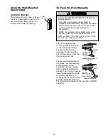
Page 31: ...oor If possible use emergency release handle to disengage trolley ONLY when garage door is CLOSED Weak or broken springs or unbalanced door could result in an open door falling rapidly and or unexpectedly NEVER use emergency release handle unless garage doorway is clear of persons and obstructions NEVER use handle to pull door open or closed If rope knot becomes untied you could fall Using the Wal...

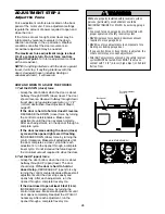
Page 32: ...t Step 3 page 29 after any adjustment of limits or force FORCE CONTROLS 1 3 9 7 5 1 3 9 7 5 LIMIT CONTROLS KG KG THE REMOTE CONTROL BATTERY NOTICE To comply with FCC and or Industry Canada rules IC adjustment or modifications of this receiver and or transmitter are prohibited except for changing the code setting or replacing the battery THERE ARE NO OTHER USER SERVICEABLE PARTS Tested to Comply wi...

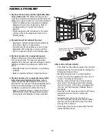
Page 33: ...or Repeat safety reverse test after adjustments to force or travel limits The need for occasional adjustment for the force and limit settings is normal Weather conditions in particular can affect door travel Refer to Adjustment Step 1 Adjust the UP and DOWN Travel Limits Decrease down travel by turning down limit adjustment screw clockwise Safety Sensor Bell Wire KG KG 1 3 9 7 5 1 3 9 7 5 1 2 3 Le...

Page 34: ...ect wires at door control touch wires together If motor unit activates replace door control If motor unit does not activate disconnect door control wires from motor unit Momentarily short across red and white terminals with jumper wire If motor unit activates replace door control wires Symptom Sending indicator light glows steadily receiving indicator light is dim or flashing Realign receiving eye...

Page 35: ...Remote Control USING THE LEARN BUTTON KG KG 1 3 9 7 5 1 3 9 7 5 1 2 3 PROGRAMMING Your garage door opener has already been programmed at the factory to operate with your hand held remote control The door will open and close when you press the large push button Below are instructions for programming your opener to operate with additional Security remote controls KG KG 1 3 9 7 5 1 3 9 7 5 1 2 3 KG K...

Page 36: ...number of accesses this temporary PIN expires and will no longer open the door It can be used to close the door even after it has expired To set a temporary PIN 1 Press the four buttons for your personal entry PIN not the last temporary PIN then press and hold the button The opener light will blink three times Release the button 2 Press the temporary 4 digit PIN you have chosen then press Enter Th...

Page 37: ... Door control button 2 41A5076 2 3 function remote control housing no circuit board 3 10A20 3V2032 Lithium battery 4 29B137 Transmitter visor clip 5 41A2828 Emergency release rope handle assembly 6 41A4353 Header bracket w clevis pin fastener 7 41B4494 1 2 conductor bell wire white white red 8 178B35 Curved door arm section 9 41A4373A Safety sensor kit receiving and sending eyes with 3 2 conductor...

Page 38: ...all labels 6 4A1344 Light socket 7 108D58 2 Lens 8 30B532 Capacitor 1 2 HP 9 12A373 Capacitor bracket 10 41A3150 Terminal block w screws 11 41D3058 Universal replacement motor bracket assembly Complete with Motor worm bracket bearing assembly RPM sensor KEY PART NO NO DESCRIPTION 12 41D328 4 Cover 13 41A2818 Limit switch drive retainer 14 41D3452 Limit switch assembly 15 41C4398A RPM sensor assemb...

Page 39: ...ully 139 53704 139 53705 139 53709 139 53680 WARRANTY SEARS WARRANTY FULL 90 DAY WARRANTY ON GARAGE DOOR OPENER For 90 days from the date of purchase Sears will repair this Garage Door Opener free of charge if defective in material or workmanship LIMITED WARRANTY From the 91st day up to 1 years from the date of purchase Sears will furnish replacement parts for any defective parts free of charge Yo...

Page 40: ...lmente 31 Mantenimiento de su abridor de puerta de cochera 32 Si tiene algún problema 33 Tabla de diagnóstico 34 Cómo Programar el Abridor 35 36 Cómo agregar o reprogramar un control remoto manual 35 Cómo borrar todos los códigos 35 Controles remotos de tres funciones 35 Cómo agregar reprogramar o cambiar un código de entrada sin llave 36 Accesorios 37 Garantía 37 Números de Servicio Contratapa CO...

Page 41: ...o está desbalanceada Una puerta de cochera que no esté bien balanceada puede no retroceder como se requiere NUNCA intente aflojar mover ni ajustar la puerta de su cochera los resortes de la puerta los cables las poleas las ménsulas ni la tornillería pues todos estos elementos están bajo tensión EXTREMA Quite TODOS los seguros y retire TODAS las cuerdas conectadas a la puerta de cochera ANTES de in...

Page 42: ...encia no funcione correctamente Vea Ajustes Paso 3 Será necesario reparar ya sea el piso o la puerta INSTALACIÓN CON UNA PUERTA SECCIONAL Si tiene una puerta de acero aluminio fibra de vidrio o con paneles de vidrio necesitará refuerzos verticales y horizontales en la puerta Instalación Paso 11 El abridor se debe instalar arriba del centro de la puerta pero si existe algún resorte de tensión o pla...

Page 43: ...erta de acceso Sensor del sistema de retroceso de seguridad Ménsula del cabezal Brazo recto de la puerta Cuerda y manija del sistema de liberación de emergencia Ménsula de la puerta Puerta de la cochera Brazo curvo de la puerta Pared delantera Riel El espacio entre la base de la puerta y el piso no debe exceder 6 mm 1 4 de pulg Trole La holgura en la tensión de la cadena es normal cuando la puerta...

Page 44: ...ra los sensores del sistema de retroceso de seguridad 2 2 Sensor del sistema de retroceso de seguridad 1 ojo emisor y 1 ojo receptor conectados a un cable de campana de dos conductores Blanco y blanco negro Su abridor viene empacado en dos cajas de cartón que contiene el motor y las piezas que se muestran en la siguiente ilustración Tome nota de que los accesorios dependerán del modelo que haya co...

Page 45: ...ro falso 2 Pasador de chaveta de 5 16x1 1 4 pulg 1 Cuerda Arandela de 5 16 pulg 6 Perno hexagonal de 5 16 18x7 8 pulg 4 Pasador de chaveta de 5 16x1 pulg 1 Tornillo de cabeza cuadrada de 1 4x1 1 2 pulg 4 Perno de coche de 1 4 20x1 2 pulg 4 Tuerca de 1 4 20 pulg 4 Tuerca de 10X32 4 Tornillo 10 32X3 8 pulg 4 Perno con arandela 5 16 18x1 2 pulg 2 montado en el abridor Perno hexagonal de 1 4 20x1 1 2 ...

Page 46: ... o molestos 3 Ensamble las tuercas de seguridad alínee y apriete NOTA Si el riel no se ensamble exactamente como se muestra el carro no se moverá suavemente a lo largo del riel o golpeará contra los pernos 4 Situar la ménsula frente al final del riel con se muestra Fijar firmement con los tornillos indicados NOTA Al apretar los pernos asegurar que la ménsula se mantenga paralela al riel De otra ma...

Page 47: ...ce demasiado Mantener una distancia de un mínimo de 5mm 2 pulg entre el carro y este perno al ajustar los límites de desplazamiento ver página 27 Perno con arandela 5 16 18x1 2 pulg Riel Sección posterior Orificio del tornillo de protección de la cubierta USAR UNICAMENTE ESTE TIPO Y TAMAÑO DE PERNO Tuerca de 5 16 18 pulg Arandela de 5 16 pulg Perno hexagonal de 5 16 18x7 8 pulg Para evitar daños S...

Page 48: ...o esté torcida 5 Quite el destornillador CUBIERTA DEL RUEDA DENTADA Insertar la lengueta posterior en la ranura en la parte posterior de la placa de montaje Oprimir la cubierta ligeramente y insertar la lengueta delantera Figura 3 Cubierta de la rueda dentada del motor Ranura de la pestaña delantera Placa de montaje Ranura de la pestaña posterior Rueda dentada del motor Figura 3 Polea de cable Rie...

Page 49: ...del control de la puerta de la cochera en la pared 11 Coloque la calcomanía que contiene la prueba de retroceso de seguridad y liberación de emergencia a plena vista en la parte interior de la puerta de la cochera 12 Al concluir la instalación pruebe el sistema de retroceso de seguridad La puerta DEBE retroceder al entrar en contacto con un objeto de 3 8 cm 1 1 2 pulg o bien con un pedazo de mader...

Page 50: ...e centímetros excede la altura disponible en su cochera use la altura máxima posible o consulte la página 13 para la Instalación en el cielo raso o plafón Puerta seccional con carril curvo Puerta de una sola pieza con carril horizontal Pared delantera Carril Punto más alto del recorrido Puerta 5 cm 2 pulg Puerta Punto más alto del recorrido 5 cm 2 pulg Carril Pared delantera Pedazo de madera de 5x...

Page 51: ...os orificios con una broca de 3 16 de pulgada y sujete la ménsula al soporte de la estructura con la tornillería que se incluye Tornillos de cabeza cuadrada de 5 16 por 9x1 5 8 pulgadas ESTAS PIEZAS SE MUESTRAN EN SU TAMAÑO REAL INSTALACIÓN DE LA MÉNSULA DEL CABEZAL EN EL CIELO RASO Extienda la línea central vertical sobre el cielo raso como se muestra en la ilustración Coloque la ménsula en el ce...

Page 52: ...sula del Cabezal Coloque el abridor sobre el piso de la cochera debajo de la ménsula del cabezal Use el hule espuma del empaque como base para protegerlo NOTA Si el resorte de la puerta está obstruyendo va a necesitar ayuda Otra persona tendrá que sostener el abridor firmemente sobre un soporte temporal para ayudarle a que el riel pueda librar el resorte Coloque la ménsula del riel junto a la méns...

Page 53: ...lg sobre su lado en la sección superior de manera que quede debajo del riel La parte superior de la puerta debe estar alineada con la parte superior de la unidad del motor No instale el abridor a más de 10 cm 4 pulg por encima de este punto INSTALACIÓN PASO 4 Coloque el Abridor en Posición Siga las instrucciones correspondientes al tipo de puerta de su cochera como se muestra en la ilustración PUE...

Page 54: ...onar la puerta manualmente Si la puerta golpea el riel suba la ménsula del cabezal NOTA NO conecte el abridor a la fuente de energía eléctrica en este momento Perno hexagonal de 5 16 18x7 8 pulg Tuerca de 5 16 18 pulg Arandela de 5 16 pulg Tornillo de cabeza cuadrada de 5 16 18x1 7 8 pulg ESTAS PIEZAS SE MUESTRAN EN SU TAMAÑO REAL Cielo raso con acabado Soporte de la estructura no visible Ménsula ...

Page 55: ...N GRAVE o INCLUSO LA MUERTE por electrocución ANTES de instalar el control de la puerta cerciórese de que la energía eléctrica no esté conectada Conecte el control SÓLO a cables de bajo voltaje de 24 VOLTIOS Para evitar la posibilidad de una LESIÓN GRAVE e INCLUSO LA MUERTE cuando la puerta de la cochera se está cerrando Instale el control de la puerta de manera que quede a la vista desde la puert...

Page 56: ... de liberación del trole exterior Ajuste el largo de la cuerda de tal manera que la manija quede a seis pies 1 83 m del piso y haga un nudo para asegurarla NOTA Si es necesario cortar la cuerda queme con un cerillo o un encendedor el extremo que cortó para sellarla y evitar que se desenrede Guía de la lente Ranura de la lente Bombillo estándar de 75 vatios máximo Lente par la luz Lengüetas de la l...

Page 57: ...terminal de cobre el cable blanco neutral al tornillo de la terminal color plata y el cable verde tierra al tornillo verde de la puesta a tierra El abridor debe de estar puesto a tierra Vuelva a poner la cubierta en su lugar y atorníllela Para evitar dificultades con la instalación no encienda ni use el abridor en este momento Para evitar la posibilidad de una LESIÓN GRAVE o INCLUSO LA MUERTE por ...

Page 58: ... de la puerta ya sea el derecho o el izquierdo siempre y cuando nunca le dé el sol directamente a la lente del ojo receptor Las ménsulas para la instalación han sido diseñadas para que se sujeten directamente al carril de la puerta sin la necesidad de tornillería ni piezas adicionales Si es necesario instalar las unidades sobre la pared asegúrese de que todas las ménsulas estén sujetas a una super...

Page 59: ...ia abajo El carro se volverá a conectar la próxima vez que accione hacia ARRIBA o hacia ABAJO Para evitar la posibilidad de una LESIÓN GRAVE o INCLUSO LA MUERTE si la puerta de la cochera se cae De ser posible use la manija de liberación de emergencia para soltar el trole SÓLO cuando la puerta de la cochera esté CERRADA Si los resortes están débiles o rotos o bien si la puerta está desbalanceada l...

Page 60: ...RECAUCIÓN ADVERTENCIA ADVERTENCIA ADVERTENCIA ADVERTENCIA ADVERTENCIA AVISO Para cumplir con las reglas de la FCC y o de Canadá IC las reglas ajustes o modificaciones de este receptor y o transmisor están prohibidos excepto por el cambio de la graduación del código o el reemplazo de la pila NO HAY OTRAS PIEZAS REPARABLES DEL USUARIO Se ha probado para cumplir con las normas de la FCC para USO DEL ...
Page 61: ...o y se vuelve a abrir sin ningún motivo aparente ajuste la fuerza o los límites del recorrido y repita la prueba de retroceso de seguridad Es normal tener que ajustar la fuerza y los límites del recorrido periódicamente Las condiciones atmosféricas pueden afectar al recorrido de la puerta Consulte el apartado Ajustes Paso 1 Ajuste los límites del recorrido hacia ARRIBA y hacia ABAJO Reduzca el rec...

Page 62: ...ente con los cables Si la unidad del motor se activa sustituya la unidad de control Si el motor no se activa desconecte del motor los cables de control de la puerta Con un cable haga puente entre los terminales rojo y blanco Si el motor se activa cambie los cables de control de la puerta Síntoma La luz indicadora de la célula transmisora permanece encendida la luz de la célula receptora es débil o...

Page 63: ...se proveen las instrucciones para programar su abridor para que opere con controles remotos Security adicionales AVISO Si utiliza este abre puertas de garaje Security con un transmisor no dotado de un sistema de códigos de salto código aleatorio se verán circunvenidas las medidas técnicas incorporadas en el receptor del abridor para proteger contra los aparatos de captura de códigos El propietario...

Page 64: ...o de accesos este PIN temporal expira y no vuelve a abrir la puerta Se puede usar para cerrar la puerta aún después de que haya expirado Haga lo siguiente para poner un PIN temporal 1 Oprima los cuatro botones correspondientes a su PIN de entrada personal no el último PIN temporal luego oprima y mantenga oprimido el botón La luz del abridor va a parpadear tres veces Suelte el botón 2 Oprima los cu...

Page 65: ...de estado a estado Sears Roebuck and Co Dept 817 WA Hoffman Estates IL 60179 Ménsulas de soporte Para cielos rasos sin acabados o en los casos en que se necesite soporte adicional basado en la construcción de la cochera Incluye las ménsulas y los sujetadores SECURITY Control remoto compacto de 3 funciones Con lazada para ponerse en el llavero SECURITY Control remoto de 3 funciones Incluye el clip ...

Page 66: ...pment and electronics call or go on line for the location of your nearest Sears Parts Repair Center 1 800 488 1222 Call anytime day or night U S A only www sears com To purchase a protection agreement U S A or maintenance agreement Canada on a product serviced by Sears 1 800 827 6655 U S A 1 800 361 6665 Canada Para pedir servicio de reparación a domicilio y para ordenar piezas 1 888 SU HOGARSM 1 ...

Reviews: