background image

Summary of Contents for 139.53648D

Page 1: ...his product Fasten the manual near the garage door after installation Leer y seguir todas las reglas de seguridad y las instrucciones de operacion antes de usar este producto por primera vez Guardar este manual cerca de la puerta de la cochera Periodic checks of the opener are required to ensure safe operation Se deben realizar revisiones peribdicas del abridor de puertas para asegurar su operacio...

Page 2: ... control 31 To open the door manually 31 Care of your garage door opener 32 Having a problem 33 Diagnostic chart 34 Programming 35 36 To add or reprogram a hand held remote control 35 To erase all codes 35 3 function remotes 35 To add reprogram or change a Keyless Entry PIN 36 Repair Parts 37 38 Rail assembly parts 37 Installation parts 37 Motor unit assembly parts 38 Accessories 39 Warranty 39 Re...

Page 3: ...balance An unbalancedgarage door may not reversewhen required NEVERtry to loosen move or adjust garage door door springs cables pulleys brackets or their hardware all of which are under EXTREME tension DisableALL locks and remove ALL ropes connected to garagedoor BEFORE installing and operating garage door openerto avoid entanglement To prevent damageto garage door and opener ALWAYSdisable locks B...

Page 4: ...eed 1 4 6 mm Otherwise the safety reversal system may not work properly See Adjustment Step 3 Floor or door should be repaired SECTIONAL DOOR INSTALLATIONS Do you have a steel aluminum fiberglass or glass panel door If so horizontal and vertical reinforcement is required Installation Step 11 The opener should be installed above the center of the door If there is a torsion spring or center bearing ...

Page 5: ...NE PIECE DOOR WITHOUT TRACK Header Wall Slack in chain tension is normal when garage door is closed FINISHED CEILING Support bracket fastening hardware is required See page 16 Door Control Safet Access Door O Reversing Sensor Gap between floor and bottom of Safety door must not exceed 1 4 6 ram Reversing Sensor Motor Unit CLOSED POSITION Cable Pulley Bracket Cable Trolley o i Door J l Em ergency R...

Page 6: ...adjustment is complete Door Control Button SECURITY 3 Function Remote Control with Visor Clip 2 C Wrap 2 Safety Reversing Sensor Mounting Bracket With Square Holes 2 Cable Door Bracket Pulley Bracket vv _ Rail J_ _J Header Bracket Sprocket Cover Safety Reversing Sensor Mounting Bracket With Slot 2 Motor Unit with Light Lens 2 Conductor Bell Wire White White Red Curved Door Arm Section 2 Safety Rev...

Page 7: ...E Lock Washer 5 16 4 i Master Link 2 Lock Nut 1 4 20x7 16 4 Lag Screw Hex Bolt 5 16 9xl 5 8 2 5 16 18x7 8 4 Nut 5 16 18 6 Lock Washer 5 16 6 5 16 18xl 7 8 2 _ading Screw 1 4 14x5 8 2 0 Ring Fastener 3 Handle Carriage Bolt 5 16 18x2 1 2 2 Drywall Anchors 2 Rope Clevis Pin 5 16 x2 3 4 1 o Clevis Pin 5 16 x1 1 4 1 Clevis Pin 5 16 x1 1 1 4 x1 1 2 4 Hex Bolt 1 4 20x1 1 2 2 Carriage Bolts 1 4 20xl 2 4 S...

Page 8: ...d or nuisance door reversals 3 Assemble lock nuts ensure alignment and tighten NOTE If rail is not assembled exactly as shown trolley will not travel smoothly along length of rail or it will hit against nuts 4 Position the cable pulley bracket on the front end of the rail as shown Fasten securely with the hardware shown NOTE When tightening the bolts be sure to keep bracket parallel to the rail Ot...

Page 9: ...king material to protect the cover For convenience put a support under the cable pulley bracket Remove the two washered bolts mounted in top of motor unit Align the holes in the back section of the rail with the holes in the motor unit Fasten the rail with the two washered bolts previously removed Tighten securely Use only these bolts Use of any other bolts will cause serious damage to door opener...

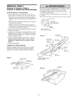
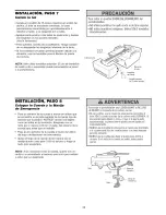
Page 10: ... threaded shaft 4 Use the second master link to connect the chain to the flat end of the shaft Figure 1 Check to make sure the chain is not twisted 5 Remove the screwdriver Leave Chain Cable Inside Dispensing Carton to Prevent Kinking ATTACHING THE SPROCKET COVER Insert the back tab in the slot on the back of the mounting plate Squeeze the cover slightly and insert the front tab Figure 3 To avoid ...

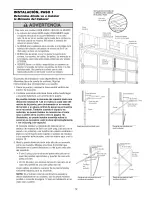
Page 11: ...LL INSTALLATION WARNINGS AND INSTRUCTIONS 2 Install garage door opener only on properly balanced and lubricated garage door An improperly balanced door may not reversewhen required and could result in SEVEREINJURYor DEATH 3 All repairs to cables spring assemblies and other hardware MUST be made by a trained door systems technician BEFORE installing opener 4 Disableall locks and removeall ropes con...

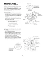
Page 12: ...h it to the ceiling see page 13 when clearance is minimal It may be mounted on the wall upside down if necessary to gain approximately 1 2 13 mm If you need to install the header bracket on a 2x4 on wall or ceiling use lag screws not provided to securely fasten the 2x4 to structural supports as shown here and on page 13 3 Open your door to the highest point of travel as shown Draw an intersecting ...

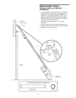
Page 13: ... Screw 5 16 9xl 5 8 Wall Mounting Holes Optional Wall Mounting Holes Header Wall 2x4 Structural Support i Horizontal Line _ t Garage _ I Door Highest Point of Vertical Garage Door Travel Centerline of Garage Door The nail hole is for positioning only You must use lag screws to mount the header bracke Vertical Centerline of Garage Door Lag Screws 5 16 9xl 5 8 CEILING HEADER BRACKET INSTALLATION Ext...

Page 14: ... ll need help Have someone hold the opener securely on a temporary support to allow the rail to clear the spring Position the rail bracket against the header bracket Align the bracket holes and join with a clevis pin as shown Insert a ring fastener to secure Ring Fastener Header Bracket 0 i _ I Clevis Pin 5 16 x2 3 4 Pulley Bracket Rail Garage Door o Opener carton or _ Temporary Support HARDWARE S...

Page 15: ...lide the outer trolley toward the motor unit The trolley can remain disconnected until Installation Step 12 is completed _ __ Tr llleYse ENGAGED Arm RELEASED To prevent damageto garagedoor rest garagedoor opener rail on 2x4 placed on top section of door ONE PIECE DOOR WITHOUT TRACK A 2x4 on its side is convenient for setting an ideal door to rail distance Remove foam packaging Raise the opener ont...

Page 16: ...8x7 8 hex bolts lock washers and nuts 6 Check to make sure the rail is centered over the door or in line with the header bracket if the bracket is not centered above the door 7 Remove the 2x4 Operate the door manually If the door hits the rail raise the header bracket NOTE DO NOT connect power to opener at this time HARDWARE SHOWN ACTUAL SIZE Lag Screw 5 16 9xl 5 8 Hex Bolt 5 16 18x7 8 Nut 5 16 18...

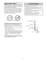
Page 17: ... motor unit panel white to 2 white red to 1 5 Position the antenna wire as shown To prevent possible SERIOUSINJURYor DEATHfrom electrocution Besure power is not connected BEFORE installing door control Connect ONLYto 24 VOLTlow voltage wires To prevent possible SERIOUSINJURYor DEATHfrom a closing garagedoor Install door control within sight of garage door out of reach of children at a minimum heig...

Page 18: ...Emergency Release Rope and Handle Thread one end of the rope through the hole in the top of the red handle so NOTICE reads right side up as shown Secure with an overhand knot at least 1 25 mm from the end of the rope to prevent slipping Thread the other end of the rope through the hole in the release arm of the outer trolley Adjust rope length so the handle is 6 feet 1 8 m above the floor Secure w...

Page 19: ...e attached 3 prong cord Connect the black line wire to the screw on the brass terminal the white neutral wire to the screw on the silver terminal and the ground wire to the green ground screw The opener must be grounded Reinstall the cover To avoid installation difficulties do not run the opener at this time To prevent possible SERIOUSINJURYor DEATHfrom electrocution or fire Besure power is not co...

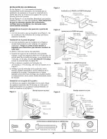
Page 20: ... lens The mounting brackets are designed to clip onto the track of sectional garage doors without additional hardware Be sure power is not connected to the garage door opener BEFORE installing the safety reversingsensor To prevent SERIOUSINJURY or DEATHfrom a closing garagedoor Correctly connect and align the safety reversing sensor This required safety device MUST NOTbe disabled Install the safet...

Page 21: ...e to locate and drill 2 3 16 diameter pilot holes on both sides of the garage door 4 6 above the floor but not exceeding 6 see warning on page 20 5 Attach bracket assembly with 1 4 xl 1 2 lag screws as shown in Figure 2 6 Adjust right and left bracket assemblies to the same distance out from mounting surface Make sure all door hardware obstructions are cleared Tighten the nuts securely Garage Door...

Page 22: ...iving eye Lock in place Loosen the receiving eye wing nut and adjust sensor until it receives the sender s beam When the green indicator light glows steadily tighten the wing nut Figure 6 C Wrap ___ Wing _ Nut Lndihtat_ Hex Bolt _ _ _ _ _ 1 4 20 x 1 1 2 _ _ _ TROUBLESHOOTING THE SAFETY SENSORS 1 If the sending eye indicator light does not glow steadily after installation check for Electric power t...

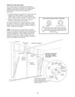
Page 23: ...e 2 Position the bracket on the face of the door within the following limits A The top edge of the bracket 2 4 5 10 cm below the top edge of the door B The top edge of the bracket directly below any structural support across the top of the door Header j Bracket Door Bracket Location Vertical of Garage Door Fiberglass aluminum or lightweight steel garagedoors WILL REQUIREreinforcement BEFORE instal...

Page 24: ...ed for your installation Refer to the dotted line optional placement drawing Drill 3 16 pilot holes and substitute 5 16 x1 1 2 lag screws not provided to fasten the bracket to the door HARDWARE SHOWN ACTUAL SIZE Nut 5 16 18 LockWasher 5 16 Carriage Bolt 5 16 18x2 1 2 Header Wall 2x4 Support Finished Ceiling Header Bracket Optional Placement of Door Bracket Door Bracket Centefline of Garage Door Ho...

Page 25: ...oin sections Select holes as far apart as possible to increase door arm rigidity Figure 3 Hole alignment alternative If holes in curved arm are above holes in straight arm disconnect straight arm Cut about 6 15 cm from the solid end Reconnect to trolley with cut end down as shown Bring arm sections together Find two pairs of holes that line up and join with bolts lock washers and nuts Proceed to A...

Page 26: ...4 complete turns Figure 5 Door Bracket Clevis Pin Straight 5 16 x1 1 4 Arm Figure 4 Ring Fastener Bolts 5 16 18x7 8 Lock Washers 5 16 Nuts 5 16 18 3urved Door Arm Press the Door Control push button The trolley will travel to the fully closed position Manually close the door and lift the door arm to the trolley The arm should touch the trolley just ahead of the door arm connector hole Refer to the ...

Page 27: ...en force as explained in Adjustment Step 2 If the door does not close completely Increase down travel Turn the down limit adjustment screw counterclockwise One turn equals 2 5 cm of travel If door still won t close completely and the trolley bumps into the pulley bracket page 4 try lengthening the door arm page 25 and decreasing the down limit If the opener reverses in fully closed position Decrea...

Page 28: ...n floor HOW AND WHEN TO ADJUST THE FORCES 1 Test the DOWN close force Grasp the door bottom when the door is about halfway through DOWN close travel The door should reverse Reversal halfway through down travel does not guarantee reversal on a 1 1 2 3 8 cm obstruction See Adjustment Step 3 page 29 If the door is hard to hold or doesn t reverse DECREASE the DOWN close force by turning the control co...

Page 29: ...out a properly installed safety reversal system persons particularly small children could be SERIOUSLYINJUREDor KILLEDby a closing garage door Safety reversalsystem MUST be tested every month If one control force or travel limits is adjusted the other control may also needadjustment After ANY adjustments are made the safety reversal system MUST be tested Door MUST reverseon contact with 1 1 2 3 8 ...

Page 30: ...rage Door Opener Your Security opener and hand held remote control have been factory set to a matching code which changes with each use randomly accessing over 100 billion new codes Your opener will operate with up to eight Security remote controls and one Security Keyless Entry System If you purchase a new remote or if you wish to deactivate any remote follow the instructions in the Programming s...

Page 31: ...emergency release handle unlessgarage doorway is clear of persons and obstructions NEVERuse handleto pull door open or closed If rope knot becomes untied you could fall The door should be fully closed if possible Pull down on the emergency release handle and lift the door manually To reconnect the door to the opener press the door control push bar MANUAL DISCONNECT POSITION The lockout feature pre...

Page 32: ...ecessary See page 11 Once a Year Oil door rollers bearings and hinges The opener does not require additional lubrication Do not grease the door tracks To prevent possible SERIOUSINJURYor DEATH NEVERallow small children near batteries If battery is swallowed immediately notify doctor The lithium battery should produce power for up to 5 years To replace battery use the visor clip or screwdriver blad...

Page 33: ...k door for balance or any binding problems Refer to Adjustment Step 2 Adjust the Force 4 My door reverses for no apparent reason after fully closing and touching the floor Repeat safety reverse test after adjustments to force or travel limits The need for occasional adjustment for the force and limit settings is normal Weather conditions in particular can affect door travel Refer to Adjustment Ste...

Page 34: ...sensors if the indicator lights glow replace the wires for the sensors If the sensor indicator lights do not light replace the safety sensors Symptom LED is not lit on door control Inspect door control wires for a short staple in wire replace as needed Disconnect wires at door control touch wires together If motor unit activates replace door control If motor unit does not activate disconnect door ...

Page 35: ...ol USING THE LEARN BUTTON 1 Press and release the learn button on the motor unit The learn indicator light will glow steadily for 30 seconds 3 Release the button when the motor unit lights blink It has learned the code If light bulbs are not installed two clicks will be heard 2 Within 30 seconds press and hold the button on the hand held remote that you wish to operate your garage door To Erase Al...

Page 36: ...move To set a temporary PiN You may authorize access by visitors or service people with a temporary 4 digit PIN After a programmed number of hours or number of accesses this temporary PIN expires and will no longer open the door It can be used to close the door even after it has expired To set a temporary PIN 36 Press the four buttons for your personal entry PIN not the last temporary PIN then pre...

Page 37: ...9B137 41A2828 41A4353 41B4494 1 178B35 41A4373A 12B374 12B380 12B483 12B484 12B485 12B776 178B34 41A3475 16 114A3130 DESCRIPTION Door control button 3 function remote control housing no circuit board 3V2032 Lithium battery Transmitter visor clip Emergency release rope handle assembly Header bracket w clevis pin fastener 2 conductor bell wire white white red Curved door arm section Safety sensor ki...

Page 38: ...d End panel w all labels Light socket Lens Capacitor 1 2 HP Capacitor bracket Terminal block w screws Universal replacement motor bracket assembly Complete with Motor worm bracket bearing assembly RPM sensor KEY PART NO NO 12 41D0328 4 13 41A2818 14 41D3452 15 41C4398A 16 41C4246 17 41A2826 18 41A2822A 19 41A5021 3H 315 20 41A3691 41A2825 DESCRIPTION Cover Limit switch drive retainer Limit switch ...

Page 39: ...n garage with low headroom clearance WARRANTY SEARS WARRANTY FULL 90 DAY WARRANTY ON GARAGE DOOR OPENER For 90 days from the date of purchase Sears will repair this Garage Door Opener free of charge if defective in material or workmanship LIMITED WARRANTY From the 91st day up to 1 years from the date of purchase Sears will furnish replacement parts for any defective parts free of charge You pay fo...

Page 40: ...idor de puerta de cochera 30 C6mo usar la unidad de control de pared 31 C6mo abrir la puerta manualmente 31 Mantenimiento de su abridor de puerta de cochera 32 Si tiene algun problema 33 Tabla de diagn6stico 34 C6mo Programar el Abridor 35 36 C6mo agregar o reprogramar un control remoto manual 35 C6mo borrar todos los c6digos 35 Controles remotos de tres funciones 35 C6mo agregar reprogramar o cam...

Page 41: ...alanceada puedeno retroceder comose requiere NUNCA intenteaflojar moverniajustarla puertade su cochera los resortesdela puerta los cables las poleas las m_nsulas ni latornillerfa puestodosestoselementos est_n bajotensi6nEXTREMA QuiteTODOS losseguros y retireTODAS las cLierdas conectadas alapuertadecochera ANTES deinstalar y operar elabridordela puertadecochera paraevitarqueseenreden Paraevitarda_o...

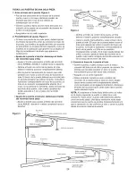
Page 42: ...sistema de retroceso de emergencia no funcione correctamente Vea Ajustes Paso 3 Sera necesario reparar ya sea el piso o la puerta INSTALACION CON UNA PUERTA SECCIONAL Si tiene una puerta de acero aluminio fibra de vidrio o con paneles de vidrio necesitara refuerzos verticaies y horizontales en la puerta Instalaci6n Paso 11 El abridor se debe instalar arriba del centro de la puerta pero si existe a...

Page 43: ...io PUERTA DE UNA SOLA PIEZA SIN CARRIL CIELO RASO CONACABADO Se requieremensula d y tomillos o sujetadores Vea la pagina 16 Pared delantera Sensor del sistemade retrocesode seguddad _ Puertade acceso o Sensor del sistemade Elespacioentre la base retrocesode seguridad la puerta y el piso no debede exeeder6 mm 1 4 de pulg La holguraen la tension de la cadenaes normal cuandola puerta se encuentracerr...

Page 44: ...ateriales de empaque hasta que la instalaci6n y el ajuste se hayan terminado Bot6nde control de la puerta SECURITY _ Controlesremoto de 3 funciones con clip parael visor 2 Poleade lacadena CubJertade la M_ nsulas para colgar ruedadentada Unidad delmotor conunlente Suporte la sPlo t erta Mordaza 2 M_nsuh para los sensores del sistema de retrocesode seguridad 2 M_ nsula del cabezal M6nsulade montaje...

Page 45: ...Tomillo de cabezacuadrada de 5 16 9xl 5 8 de pulg 2 Tornillode cabeza cuadrada de 5 16 18xl 7 8 pulg 2 Pemo hexagonal de 5 16 18x7 8pulg 4 Tuemade 5 16 18pLllg 6 Arande ade 5 16pulg 6 Anillo sujetador 3 Manija 1 4 14x5 8 2 Pasadorde chaveta de 5 16x2 3 4pulg 1 Pemo de coche de 5 16 18x2 1 2pulg 2 Tornillo de cabezacuadrada de 1 4x1 1 2pulg 4 Pemo hexagonal de 1 4 20x1 1 2 2 Pemo de ooche de 1 4 20...

Page 46: ...del carro y tambien movimientos de reversa de la puerta ruidosos o molestos 3 Ensamble las tuercas de seguridad alfnee y apriete NOTA Si el riel no se ensamble exactamente como se muestra el carro no se movera suavemente a Io largo del riel o golpeara contra los pemos 4 Situar la mensula frente al final del riel con se muestra Fijar firmement con los tornillos indicados NOTA AI apretar los pemos a...

Page 47: ...car un soporte abajo de la mensula Quitar los dos pernos con arandela montados en la parte superior del motor Alinear los orificios de la seccidn posterior del riel con los orificios en el motor Fijar el riel con los dos pernos previamente colocado y ajustado firmemente iSblo se deben utilizar estos pernos Cualquier otro perno pueda ocasionar serios daSos al abridor Insertar el pemo hexagonal 5 16...

Page 48: ...igura 1 Comprobar y asegurarse que la cadena no este torcida 5 Quite el destornillador CUBIERTA DEL RUEDA DENTADA Insertar la lengueta posterior en la ranura en la parte posterior de la placa de montaje Oprimir la cubierta ligeramente y insertar la lengueta delantera Figura 3 Figura 3 Cubiertade la rueda dentada de1 motor Ranura de la Ranurade la fY___ pestalia delantera Placa cJe _ montaje _ Para...

Page 49: ...ceda cuando se requiera Io que podria ocasionar una LESION GRAVEo INCLUSOLA MUERTE 3 Todaslas reparacionesde los cables resortes y otras piezas las DEBEIlevar a cabo unt_cnico especializadoen sistemas de puertas ANTESde instalar el abridor 4 Quitetodos los seguros y retire todas las cuerdas conectadas a la puerta de la cochera ANTESde instalar el abridor para de evitar que se enreden 5 Instale el ...

Page 50: ...ien cuando el espacio es reducido se puede instalar la meneula en el cielo raso o plafon de la cochera vea la pagina 13 Asimismo se puede instalar invertida sobre la pared si es necesario esto le dara aproximadamente 1 cm 1 2 pulg de espacio Si necesita instalar la mensula del cabezal en un pedazo de madera de 5x10 cm 2x4 pulg ya sea en la pared o en el techo use tornillos de cabeza cuadrada o pij...

Page 51: ...apuerta delacochera Este orificioessolamente para marcarla posicion de la mensula Se deben de utilizarlostornillos tirafondo para sujetar la m_nsula Lineacentral vertical de la puerta de garaje Tornillosde cabeza cuadradade 5 16xgxl 5 8 pulgadas Resortede la puerta Puertadela cochera vertical de la puerta de garaje INSTALACION DE LA M NSULA DEL CABEZAL EN EL CIELO RASO Extienda la linea central ve...

Page 52: ...r el abridor firmemente sobre un soporte temporal para ayudarle a que el riel pueda librar el resorte Coloque la mensula del riel junto a la mensula del cabezal Alinee los orificios de las mensulas y jQntelas con un pasador de chaveta como se muestra en la ilustraci6n Sujetelos con un anillo sujetador Riel del cabezal Pasadorde Chaveta 5 16 x2 3 4 poba de la cane Riel Puertade lacochera Caja del a...

Page 53: ...rno hacia el motor El trole puede permanecer desconectado hasta el final del Paso 12 de la secci6n de Instalaci6n Paraevitar que la puerta de cochera sufra daSos apoye el riel del abridor de la puerta de cochera sobre un pedazode madera de 5x10 cm 2x4 pulg colocado en la secciOnsuperior de la puerta RM I i iii iii iiiii Brazode iberaci6n del trole CONECTADO SUELTO PUERTA DE UNA SOLA PIEZA SIN CARR...

Page 54: ...bezal si la mensula no esta centrada sobre la puerta 7 Quite el pedazo de madera de 5x10 cm 2x4 pulg Haga funcionar la puerta manualmente Si la puerta golpea el riel suba la mensula del cabezal NOTA NO conecte el abridor a la fuente de energfa electrica en este momento ESTAS PIEZAS SE MUESTRAN EN SU TAMAI_IO REAL Tornllo de cabezacuadrada de 5 16 18xl 7 8 pulg Pemohexagonal de 5 16 18x7 8pulg Tuer...

Page 55: ... 5 Coloque el cable de la antena como se indica Paraevitar la posibilidad de una LESIONGRAVEo INCLUSOLA MUERTE pot electrocuci6n ANTESdeinstalar el control de la puerta cerci6resedeque la energiael6ctrica no est6conectada Conecteelcontrol SOLOa cablesdebajovoltajede24 VOLTIOS Paraevitar la posibilidad de una LESIONGRAVEe INCLUSO LA MUERTEcuandola puerta de la cocherase est cerrando Instale el cont...

Page 56: ...la cuerda a traves del orificio que se encuentra en la parte superior de la manija roja de manera que la palabra NOTICE aviso sea legible como se indica en la ilustraci6n Asegt rela con un nudo por Io menos a 25 mm 1 pulg del extremo de la cuerda para evitar que se resbale Pase el otro extremo de la cuerda a traves del orificio del brazo de liberaci6n del trole exterior Ajuste el largo de la cuerd...

Page 57: ...hera DEBENcumplir con todos los c6digos locales de construcci6n y el_ctricos NUNCAuse una extensidn ni un adaptador de dos hilos tampoco modifique la clavija para poder enchufarla Aseg_rese de que el abridor est_ puesto a tierra Si la reglamentacion local exige que su abridor tenga cableado permanente siga los siguientes pasos Para conectar el abridor a la corriente electrica de forma permanente a...

Page 58: ...a cochera ANTESde instalar el sensor del sistema de retroceso de seguridad Paraevitar una LESIONGRAVEo INCLUSOLA MUERTE cuando la puerta de la cochera se est_ cerrando Conecte y alinee correctamente el sensor del sistema de retroceso de seguridad Estedispositivo de seguridad es necesarioy NO SE DEBEdesactivar Instale el sensor del sistema de retroceso de seguridad de maneraque el rayo NO ESTEa m_s...

Page 59: ... la puerta del garaje a una distancia de 4 de pulg a 6 de pulg del piso no mas de 6 de pulg vease la advertenciaen la pagina 20 5 Fije la mensula completa con tirafondos de 1 4 de pulg x 1 1 2 de pulg tal como se muestra en la Figura 2 6 Verifique que las mensulas de la izquierda y de la derecha queden separadas la misma distancia de la superficie de montaje Compruebe que no hayan quedado accesori...

Page 60: ...a de mariposa Afloje la tuerca de mariposa del sensor receptor del rayo y reajuste hasta que reciba el rayo del sensor emiser Una vez que la luz verde brille continuamente apriete la tuerca de mariposa Figura 7 Cablede eampana Cielo raeo con acabado Figura 6 _ Luz Perno hexagonal _ V _ _ _ _ 1 4 20x1 1 2de pulg_ _ DIAGNOSTICO DE FALLAS CON RESPECTO A LOS SENSORES DEL SISTEMA DE REVERSA DE SEGURIDA...

Page 61: ...la sobre la parte frontal de la puerta dentro de los Ifmites siguientes A El borde superior de la mensula 5 10 cm 2 4 pulg debajo del borde superior de la puerta En el caso de puertas de fibra de vidri0 aluminio o acero ligero ES NECESARIO colocar un refuerzo ANTES de instalar el marco de la puerta P6ngase en contacto con el fabricante de su puerta para obtener un kit de refuerzo ESTAS PIEZAS SE M...

Page 62: ...racion de colocacion opcional sehalada con la Ifnea punteada Taladre dos orificios de 3 16 de pulg y sujete la mensula a la parte superior de la puerta con tomillos de cabeza cuadrada de 5 16xl 1 2 pulgadas no se incluyen ESTAS PIEZAS SE MUESTRAN EN SU TAMAI_IO REAL de pulgada Arandela de 5 16de pulgada Perno de cochede 5 16 18per 2 1 2 pulgada Pared delantera Maderade 5xlO cm Cielo raso con acaba...

Page 63: ...entar la rigidez del brazo de la puerta Figura 3 Opciones para alinear los orificios En caso de que los orificios del braze curve no se puedan alinear con los orificios del braze recto desconecte el brazo recto y corte aproximadamente 15 cm 6 pulg del extremo que no tiene orificios Vuelva a conectarlo al trole con el extremo cortado hacia abajo como se muestra Junte las dos secciones de los brazos...

Page 64: ... Figura 5 Troleintemo Troleen la posici6ncompletamentecerrada Orificio conectordel brazo de la puerta Brazode la puerta Manijade emergencia cerrada Troleintemo Mensulade a puerfa _4_ Anillosujetador Tuerca de I _T _ _ _2_ Arandela de pulgadas _16 de pulgada I I_1 pa zo o J de ulGada Pern s de _ _ _ _ _ _ _ de pulgada Brazocurvo Figura 4 Oprima el boton de control de la puerta el trole debera ir ha...

Page 65: ...a direccion opuesta alas manecillas del reloj cada vuelta del tornillo equivale a 5 cm 2 pulg del recorrido Si aQn despues de este ajuste y del trole contra mensula de la polea del cable page 4 la puerta continQa sin cerrar completamente alargue el braze de la puerta pagina 25 y disminuya el Ifmite del recorrido hacia abajo 27 Si el sistema de retroceso deseguridad no se ha instalado debidamente l...

Page 66: ... hasta que la puerta complete un ciclo de cerrado Despues de Ilevar a cabo el ajuste haga funcionar el abridor durante un ciclo completo del recorrido No aumente la fuerza mas del mfnimo necesario para cerrar la puerta 2 Pruebe la fuerza del recorrido hacia arriba abrir Sujete la puerta manualmente agarrandola por la parte inferior y detengala mg_so menos a la mitad del recorrido HACIAARRIBA abrir...

Page 67: ...ebidamente las personas y los ni_os peque_os en particular podr an sufrir LESl0NES GRAVESo II CLUS0 LA MUERTEcuando se cierra la puerta de la cochera Elsistema de retroceso de seguridad SE DEBEprobar cada rues Si se ajusta uno de los controles l mites de la fuerza o del recorrido es posible que seanecesario ajustar tambi6n el otro control Despu6s deIlevar a cabo CUALQUIER ajuste SE DEBEprobar el s...

Page 68: ...NTES de Ilevar a cabo cualquier reparaciOno de quitar las cubiertas 15 CONSERVEESTASINSTRUCCIONES C6mo usar su abridor de puerta de cochera Su abridor Security y el control remoto manual han sido programados en la fabrica con un cddigo coincidente que cambia cada vez que se usa accesando al azar mas de 100 000 millones de cddigos nuevos Su abridor funcionara hasta con 8 controles remotos Security ...

Page 69: ... entrada a la cochera est6 libre de obstrucciones y no haya ninguna persona presente NUNCAcisela manija para halar la puerta para abrirla o cerrarla Si el nudo de la cuerda se suelta usted podria caerse Si es posible la puerta se debe cerrar completamente Jale la manija del desenganche de emergencia y levante la puerta manualmente Para volver a conectar la puerta al abre puertas oprima la barra pu...

Page 70: ...la pagina 11 Una vez al a_o Ponga aceite en los rodillos los cojinetes y las bisagras de la puerta El abridor no necesita lubricaci6n adicional No lubrique los carriles de la puerta Paraevitar la posibilidad de LESIONESGRAVESo INCLUSO LA MUERTE NUNCApermita que los niSospequeSosest cerca de las bater as Si alguien se traga una bater a Ilame al m6dico de inmediato La baterfa de litio debe producir ...

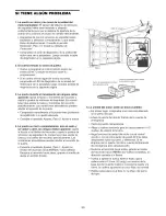
Page 71: ...a puerta tiene problernas de equilibrado o si queda atascada Consulte el apartado Ajustes Paso 2 Ajuste la fuerza 4 La puerta se cierra completamente toca el suelo y se vuelve a abrir sin ningt3n motivo aparente ajuste la fuerza o los limites del recorrido y repita la prueba de retroceso de seguridad Es normal tener que ajustar la fuerza y los limites del recorrido periodicamente Las condiciones a...

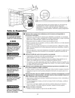
Page 72: ...ula receptora Alinee los sensores Si las luces indicadoras se encienden sustituya los cables de los sensores Si las luces de los sensores no se encienden sustituya los sensores de seguridad S ntoma El LED del control de la puerta no se enciende Inspeccione la unidad de control de la puerta cable para ver si tienen un cortocircuito grapa clavada en el cable y sustituya Io que proceda Desconecte los...

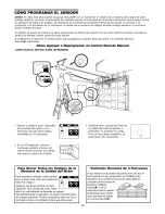
Page 73: ...or La luz indicadora de este bot6n estara encendida per 30 segundos 3 Suelte el botdn cuando las luces de la unidad del motor empiecen a parpadear Ya aprendio el cddigo Si no se hart puesto bombillos se escucharan dos chasquidos 2 En los 30 segundos optima y mantenga oprimido el boton del control remoto manual que desee usar para su puerta de cochera Para Borrar Todos los C6digos de la Memoria de ...

Page 74: ...Usted puede autorizar el acceso a sus visitas o a personal de servicio con un PIN temporal de cuatro digitos Despues de un determinado nQmero de horas programadas o nQmero de accesos este PIN temporal expira y no vuelve a abrir la puerta Se puede usar para cerrar la puerta aQn despues de que haya expirado Haga Io siguiente para poner un PIN temporal 1 Oprima los cuatro botones correspondientes a s...

Page 75: ...ra reducir la altura del recorrido de la puerta Para usarse cuando se instala el abridor en una cochera con poca tolerancia altura GARANTiA GARANT A SEARS ENTRE CASA GARANTiA DE 90 DiAS PARA EL ABRIDOR DE PUERTA DE COCHERA CRAFTSMAN Por 90 dias a partir de la fecha de compra Sears reparara este Abridor de Puerta de Cochera Craftsman sin cargo alguno si se determina que esta defectuoso en su materi...

Page 76: ...e garage door openers and water heaters 1 800 4 1VlY HOIVlE 1 800 469 4663 www sears corn www sears ca Our Home HHHHHHHHH HHHHHHHHH For repair of carry in items like vacuums lawn equipment and electronics call or go on line for the location of your nearest Sears Parts Repair Center HHHHHHHHi_ HHHHHHHHi_ 1 800 488 1222 www sears com 114A3130 Registered Trademark TMTrademark sMService Mark of Sears ...

Reviews: