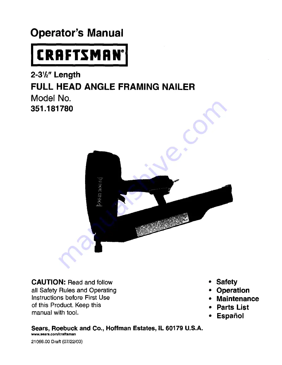
Craftsman 18178 - Full Head Framing Nailer, Operator'S Manual
The Craftsman 18178 Full Head Framing Nailer is a powerful tool designed for heavy-duty framing projects. To ensure safe and efficient operation, it is crucial to refer to the Operator's Manual. Download this manual for free from our website 88.208.23.73:8080 to gain detailed instructions and expert tips on using this exceptional tool.
Share
Download

Reviews:
No comments
Related manuals for 18178 - Full Head Framing Nailer
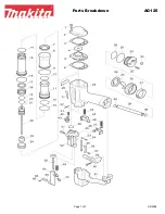
AG125
Brand: Makita Pages: 3
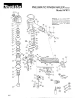
AF631
Brand: Makita Pages: 2
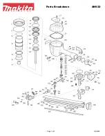
AN922
Brand: Makita Pages: 3
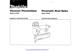
AF503
Brand: Makita Pages: 32
AN621
Brand: Makita Pages: 3
AN942
Brand: Makita Pages: 7
DBN500
Brand: Makita Pages: 24
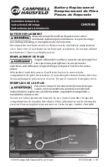
CHN71500
Brand: Campbell Hausfeld Pages: 2
CHN70600
Brand: Campbell Hausfeld Pages: 2
IronForce IFN2190
Brand: Campbell Hausfeld Pages: 12
CHN70800
Brand: Campbell Hausfeld Pages: 1

RH Series
Brand: D'Orly Pages: 11
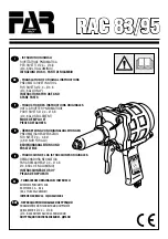
Rac 83
Brand: FAR Pages: 32
PET 25 A1
Brand: Parkside Pages: 44
PDRS 6.3 A1
Brand: Parkside Pages: 71
PAT 20-Li A1
Brand: Parkside Pages: 89

PSN90
Brand: Paslode Pages: 15
PHET 15 A1
Brand: Parkside Pages: 35


