background image

Summary of Contents for 247-770550

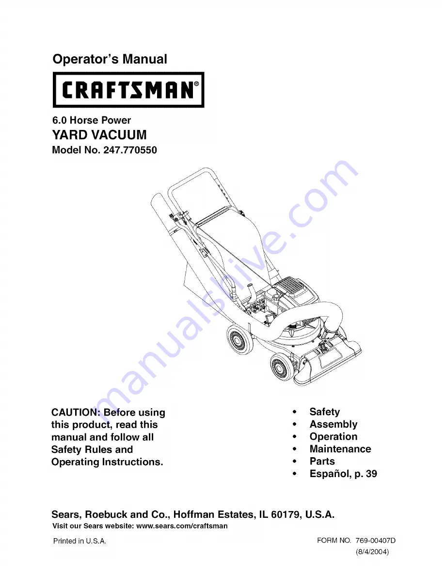
Page 1: ...ing this product read this manual and follow all Safety Rules and Operating Instructions Safety Assembly Operation Maintenance Parts Espahol p 39 Sears Roebuck and Co Hoffman Estates IL 60179 U S A Visit our Sears website www sears com craftsman Printed in U S A FORM NO 769 00407D 8 4 2004 ...

Page 2: ...zed pieces of wood or impacting objects that bend the frame or crankshaft or over speeding the engine Repairs necessary because of operator negligence including but not limited to electrical and mechanical damage caused by improper storage failure to use the proper grade and amount of engine oil or failure to maintain the equipment according to the instructions contained in the operator s manual E...

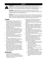
Page 3: ...arge opening Contact with the rotating impeller can amputate fingers hands and feet 8 Never attempt to unclog either the feed intake or discharge opening remove or empty vacuum bag or inspect and repair the machine while the engine is running Shut the engine off and wait until all moving parts have come to a complete stop Disconnect the spark plug wire and ground it against the engine PREPARATION ...

Page 4: ...or change vacuum bag while the engine is running Rear end of vacuum bag must be kept closed at all times during operation 9 Never operate without either the inlet nozzle or optional hose attachment properly attached to the machine Never attempt to attach or change either attachment while the engine is running 10 Keep all guards deflectors and safety devices in place and operating properly 11 Keep ...

Page 5: ...Durability Period and the Air Index Sears Roebuck and Co U S A makes this information available to the consumer on our emission labels The Emissions Durability Period describes the number of hours of actual running time for which the engine is certified to be emissions compliant assuming proper maintenance in accordance with the Operating Maintenance Instructions The following categories are used ...

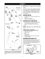
Page 6: ...r s manual are also included in the car ton See Figure 1 OPENING CARTON Cut each corner of the carton vertically from top to bottom Remove all loose parts Remove loose packing material REMOVING UNITFROM CARTON Lift unit from the rear to detach it from underlying carton material and roll unit out of carton Check carton thoroughly for any other loose parts NOTE Make sure not to crimp cables while re...

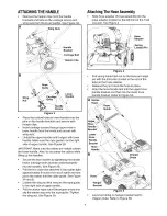
Page 7: ... the handle See Figure 3B Pull the two cable ties attached to the cables tight approximately 8 inches from each cable end and place the cables into the cable guide See Figure 3A and B Loosen the wing nut that secures the rope guide to the right side of upper handle Pull the starter rope out of the engine slowly and slip the starter rope into the rope guide Tighten the wing nut See Figure 5A Attach...

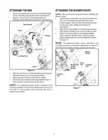
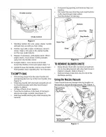
Page 8: ...andle when securing the bag or engine will not start ATTACHING THEBLOWER CHUTE NOTE The bag must be removed before installing the blower chute Grasp blower chute with one hand and slide lock ing rod on mounting bracket with other hand toward engine Use the end of mounting bracket as leverage when sliding the locking rod See Figure 7 Slip blower chute over rim of discharge opening and release locki...

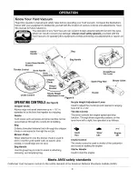
Page 9: ...mpeller for chipping Nozzle Yard waste such as leaves and pine needles can be vacuumed up through the nozzle for shredding Bag Collects shredded material fed in through the chipper chute or vacuumed in through the nozzle Blower Chute When attached to unit the blower chute is used to blow or scatter yard waste such as leaves pine needle or small twigs across yard Bag Handle Used to grasp bag in ord...

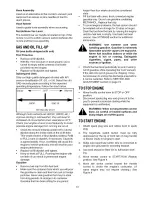
Page 10: ...soline that may be stale from long periods of storage in its container Gasoline that has been sitting for any period longer than four weeks should be considered stale Fill fuel tank with clean fresh unleaded regular gasoline only Do not use gasoline containing METHANOL Replace fuel cap To avoid engine problems the fuel system should be emptied before storage for 30 days or longer Drain the fuel fr...

Page 11: ... lock rod on mounting bracket with other hand toward engine to release Lift bag off back of unit Refer to Twist the two buttons on the back of the bag to unlock and empty contents See Figure 10 Hold bag handle and bag clip while emptying the contents Compress bag opening and fold inner flap over opening Fold outer flap over inner flap and insert buttons on the bag through metal outlets Twist the b...

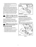
Page 12: ... as instructed in Service and ADJUSTMENTS on page 15 For best performance it is also important to keep the chipper blade sharp _ WARNING Do not at any time make any adjustments without first stopping engine and disconnecting spark plug wire Usingthe Hose Assembly Place nozzle hose vac handle in the bottom position on the nozzle to redirect vacuum to the hose assembly See Figure 12 The spring loade...

Page 13: ... Refer to Figure 19 on page 16 Nozzle height adjustment levers Lubricate nozzle height adjustment levers with light oil Refer to Figure 8 Locking Rod Lubricate the lock rod and compression springs which attach to the mounting bracket Refer to Figure 7 CLEANEQUIPMENT Clean the Yard Vacuum thoroughly after each use Wash the bag periodically with water Allow to dry thoroughly in the shade If the flai...

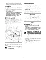
Page 14: ... place and tighten screw Figure 14 NOTE If the filter is tom or damaged in any way replace it WARNING Temperature of muffler and nearby areas may exceed 150 F 65 0 Avoid these areas SERVICE SPARK PLUG Clean the spark plug and reset the gap to 030 at least once a season or every 50 hours of operation See Figure 15 Spark plug replacement is recommended at the start of each season Refer to engine par...

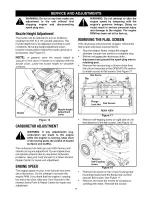
Page 15: ...peed on your Yard Vacuum has been set at the factory Do not attempt to increase the engine RPM If you think that the engine is running too fast or too slow take your Yard Vacuum to the nearest Sears Parts Repair Center for repair and adjustment 15 WARNING Do not attempt to alter the engine speed by tampering with the engine s governor linkage Doing so could result in serious personal injury and da...

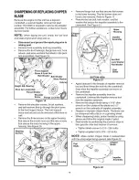
Page 16: ... flange lock nut that secures flail screen to the lower housing The flail screen does not have to be removed Refer to Figure 17 Remove the hex bolt lock washer and flat washer that secure the impeller assembly to the crankshaft See Figure 21 o_Upper _Housing Impeller JAssembly Hex Bolt Lock Washer Flat Washer _Flail Blade BOTTOM VIEW Figure 21 Apply lubricant to the threads of impeller removal too...

Page 17: ... Fuel stabilizer is an acceptable alternative to emptying the tank of fuel in minimizing the formation of fuel gum deposits during storage Add stabilizer to gasoline in fuel tank or storage container Do not drain the gas tank and carburetor if using fuel stabilizer In all cases drain all the oil from the crankcase this should be done after the engine has been operated and is still warm and refill ...

Page 18: ...ve CHOKE to ON position 5 Clean adjust gap or replace 6 Safety switch must be depressed by the front tab on the bag handle when securing the bag 7 Connect safety switch wire to engine connector and ground to mounting bracket 1 Connect and tighten spark plug wire 2 Move choke lever to OFF position 3 Disconnect fuel line at carburetor to drain fuel tank fill tank with clean fresh gasoline Fuel will ...

Page 19: ...Sears Craftsman 6 0 H P Yard Vacuum Model 247 770550 2 13 12 15 48 47 46 27 5O 54 19 ...

Page 20: ...afety Switch 49 710 3288 Safety Switch Cover 50 723 0295 Hex Washer Screw 10 16 x 50 51 749 1270 Wire Harness 52 764 0648 Cotter Pin 53 07071 Compression Spring 54 731 2292 Mounting Bracket 55 736 0607 Lock Rod 56 726 0139 Hex Cap Screw 5 16 18 x 4 5 Part Description Hex Cap Screw 5 16 18 x 625 Hex Washer Screw 3 8 16 x 1 25 Hex Cap Screw 1 4 20 x 620 Hose Base Adapter E Ring 500 Dia Compression S...

Page 21: ...Sears Craftsman 6 0 H P Yard Vacuum Model 247 770550 8 2 11_ 10 7 63 14 40 55 53 15 36 49 42 51 19 L 15 35 52 21 ...

Page 22: ...Door 58 631 0090 Torsion Spring 59 764 0631A Cap Speed Nut 1 4 60 631 0083 Pivot Rod 61 710 0726 Nozzle Door Lever 62 736 0247 Hex Screw 8 18 x 1 25 63 736 0217 Shoulder Spacer 64 710 0818 Extension Spring 723 0400 Nozzle Door Torsion Spring Part Description Nozzle Door Front Wheel Support Brace Rear Wheel Support Brace Handle Bracket Ass y RH Handle Brkt Ass y LH Not Shown Cotter Pin Bell Washer ...

Page 23: ...VALVE GASKET SET 287 358 ENGINE GASKET KIT 20 20A _ 183 _ 524 _ 585 8 617 668 O 883 J 158 46 43 374 1099 20 1102 24 357 357A 22 12 524 88 40 868 33 _ 35 34 _ 20 20A 15A Illustrations cover a range of engines Parts shown without corresponding text may not be used on your specific engine 0990 2 Assemblies include all parts shown in frames 23 ...

Page 24: ...TEM 121 CARBURETOR OVERHAUL KIT _ 276 617 0 104q_ 137_ 633 127_ 633A _ 127A_ 163_ 977 CARBURETOR GASKET SET 276 633 163_ 617 _ 633A Illustrationscover a range of engines Parts shown without corresponding text may not be used on your specific engine 0990 3 Assemblies include all parts shown in frames 24 ...

Page 25: ...968A 968B _ 443A _ 966AI 159 _ 970 _ 443_ _ 883J 77 _ _ 7_ 613A_ 836A 9 836 836_ Illustrations cover a range of engines Parts shown without corresponding text may not be used on your specific engine 0990 4 Assemblies include all parts shown in frames 25 ...

Page 26: ...3 843A _ 188 621 268 _26_9 _270 _ _1187AI I _ 601 601A _e 621 267 _ 267 _ 267A 271 265 _ 265A _ 265B 624 2O2 624A 489 _ 562 _ 505 615 404 616 Illustrations cover a range of engines Parts shown without corresponding text may not be used on your specific engine 0990 5 Assemblies include all parts shown in frames 26 ...

Page 27: ...A 564A_ 969A 969A 921D 921C 969 921E 930A 930 921F 37 78 304A 304 305 1036 EMISSION LABEL I 1229 Illustrationscover a range of engines Parts shown without corresponding text may not be used on your specific engine 0990 6 Assemblies include all parts shown in frames 27 ...

Page 28: ...4 101A 455 592 59A 455A 946 _ 65 55 592 6_ 1211 1210_ 459_ 689 _ 456 597 _ 946 73A 332 455 _73_ 363 Illustrations cover a range of engines Parts shown without corresponding text may not be used on your specific engine 0990 7 Assemblies include all parts shown in frames 28 ...

Page 29: ...59 940 _ 627 347 497 5oo 990A _ 507 520 359 373 _ 697 742 937 783 651 784_ 78s_ 513 783A 8 801 310 I 1236 1009 236 _ 74_ i __J 922_ 12o8i 942 923A Illustrationscover a range of engines Parts shown without corresponding text may not be used on your specific engine 0990 8 Assemblies include all parts shown in frames 29 ...

Page 30: ... 1770 1771 1784 1919 1920 1926 1932 1935 1936 1941 1942 1943 1947 1966 1973 1976 1977 1983 1985 1988 1991 1992 2350 2644 2669 2676 3130 3132 3166 3169 3181 3313 3314 3315 694059 Crankshaft Used Before Code Date 97011300 Used on Type No s 0866 0868 0873 0877 1166 1170 1332 1366 1368 1370 1371 1544 1559 1569 1977 691455 Crankshaft Used After Code Date 97011200 Used on Type No s 1149 1548 1925 2312 2...

Page 31: ...y 020 Oversize Used Before Code Date 97011300 499432 Piston Assembly 030 Oversize Used After Code Date 97011200 493387 Piston Assembly 030 Oversize Used Before Code Date 97011300 PART NO 26 499425 27 691866 DESCRIPTION Ring Set Standard Used After Code Date 97011200 Note 493261 Ring Set Standard Used Before Code Date 97011300 499426 Ring Set 010 Oversize Used After Code Date 97011200 493388 Ring S...

Page 32: ...d After Code Date 96060200 Used on Type No s 0662 1315 1367 1538 1762 1934 1947 1949 1982 1989 2312 2313 2314 2315 2316 2330 2351 2352 2360 2378 2385 2394 3115 3173 493738 Camshaft Counterclockwise Used Before Code Date 96060300 Used on Type No s 1538 50 497465 51 272199 54 691650 55 691421 58 280399 60 281434 65 690837 78 691108 81 691740 83 691778 95 691636 97 493267 98A 493280 101 691623 104 e6...

Page 33: ...391 2635 2673 2681 3178 3183 Note 498965 Carburetor 187C Choke System Used on Type No s 0664 0665 0666 0667 0671 0672 1149 1167 1170 188 1368 1369 1370 1373 1548 190 Plug Welch Valve Throttle 202 Note 696564 Valve Throttle Primer System Used After Code Date 01040800 133 398187 134 e398188 137 et693981 146 690979 159 691753 163 e 272653 187 691050 691371 692042 696292 690877 690940 691829 Float Car...

Page 34: ...571 1721 1752 1754 1756 1761 1762 1764 1770 1771 1784 1922 1928 1934 1937 1938 1947 1949 1977 1978 1982 1983 1987 1989 1990 2312 2314 2316 2319 2323 2326 2328 2330 2348 2351 2371 2372 2378 2381 2384 2385 2386 2387 2388 2389 2390 2394 2395 2396 2632 2634 2641 2642 2643 2644 2645 2646 2647 2348 2670 2671 2672 2675 2676 2680 2682 2684 2685 3115 3116 3122 3124 3127 3128 3129 3132 3172 3173 3174 3180 3...

Page 35: ...2329 2331 2349 2350 2367 2383 2391 2635 2669 2673 2681 3110 3120 3123 3133 3167 3176 3178 3179 3183 695892 Housing Blower Used on Type No s 1721 1784 1989 2320 2360 2370 2384 2385 2386 2389 2390 2394 2395 2641 2643 2646 2684 2685 3129 3180 3182 3308 3509 696298 Housing Blower Used on Type No s 1717 1718 1719 1754 2326 3181 REE PART NO NO 305 691108 306 690450 307 690345 309 695550 310 692327 332 6...

Page 36: ...21 692310 Switch Stop 627 692872 Bracket Stop Switch 633 e 691321 Seal Choke Throttle Shaft Throttle 633A et693867 Seal Choke Throttle Shaft Choke 635 66538 Boot Spark Plug 651 93490 Screw Starter Gear Cover 664 691087 Nut Key Switch 668 493823 Spacer Includes 2 670 692294 Spacer Fuel Tank 676 396548 Deflector Muffler Louvered 676A 393756 Deflector Muffler Side Out 676B 397931 Deflector Muffler Di...

Page 37: ...over Blower Housing Used on Type No s 1520 1530 1531 1567 2611 2612 2630 2631 2667 2678 Cover Blower Housing Black Cover Blower Housing Static Guard XTE Used on Type No s 2320 2331 2626 2391 2396 Cover Blower Housing Static Guard Satin Black Used on Type No s 2324 2384 2385 2386 2387 2388 2389 2390 2394 2395 Cover Blower Housing Cover Blower Housing Spring Brake Spring Brake 923 691994 923A 695891...

Page 38: ... Date 97052500 and Before Code Date 99010100 499340 Emission Label Used Before Code Date 97052600 697378 Emission Label Used on Engines with Trim D1 275177 Owner s Manual Note 274940 Owner s Manual Used on Type No s 1717 1718 1719 1754 2326 1095 498528 1102 691266 1119 691648 1160 691627 1210 498144 1211 498144 1236 695959 Kit Screw Washer Note 696293 Kit Screw Washer Used on Type No s 1717 1718 1...

Page 39: ...NTIA DE SERVICIO ESTA DISPONIBLE PONIENDOSE EN CONTACTO CON EL CENTRO DE SERVICIO SEARS MAS CERCANO EN EE UU ESTA GARANTIATIENE VALIDEZ SOLAMENTE MIENTRAS EL PRODUCTO SE ENCUENTRA EN USO EN LOS ESTADOS UNIDOS Esta garantfa le da derechos legales especificos y usted puede tener otros derechos los cuales varfan de un estado a otro Sears Roebuck and Co D 817WA Hoffman Estates II 60179 ASPIRADORA PARA...

Page 40: ...t mucho cuidado de no incluir pedazos de metal rocas botellas latas u otros objetos extrahos Se podrfa causar lesiones personales o daSar la maquina Siempre usar anteojos o gafas de seguridad durante el manejo y mientras se hacen ajustes o reparaciones para protegerse los ojos contra objetos extrahos que puedan ser lanzados por la maquina Usar zapatos de trabajo gruesos y con suela aspera y pantal...

Page 41: ...es y sus vapores son explosives Guardar el combustible y el aceite en contenedores aprobados lejos del calory llamas expuestas y lejos del alcance de los nifios Revisar el nivel y cargar combustible antes de arrancar el motor Nunca quitar la tapa del tanque de combustible ni afiadir combustible mientras el motor esta funcionando Siempre dejar que el motor se enfrie por Io menos durante dos minutes...

Page 42: ...idad inferior y de la unidad del rodillo de cart6n Controle el cart6n a conciencia para saber si hay cualquier otra pieza floja PIEZASSUELTAS Ver la figura 1 Montaje del manillar Recolector bolsa Montaje del tubo de soplado Anteojos de seguridad no se muestran Botella de 20 onzas de aceite para motor Manual del operador DESCONEXION DELABUJIA Antes de comenzar a armar la nueva aspiradora para jardi...

Page 43: ...rte lateral de la manija superior Consulte Figure 4 Manguera Resorte Figure 4 Una a presi6n la manija de la manguera con el soporte de la manija inferior para ajustarla en su lugar y coloque el caSo de la manguera en el gancho del soporte lateral que se encuentra pr6ximo al canal de la cortadora Consulte Figura 7 INSTALACION DELRECOLECTOR Asir el mango del recolector con una mano y con la otra man...

Page 44: ...adedescarga y soltar lavarilladefijaci6n parasujetar eltuboensulugar Cuando sevaausareltubodesoplado elevar la boquilla alaposici6n mas alta Verelajuste dela boquilla enlasecci6n AJUSTES NOTE El boron interruptor de seguridad adosado a la escuadra de montaje debe quedar totalmente oprimido por la lengdeta delantera ubicada en tubo de soplado de Io contrario el motor no arrancara Cierre de Barra To...

Page 45: ...Permite introducir ramillas y ramas peque_as de hasta 1 1 2 de diametro en el rotor para astillarlas Boquilla Los desechos del jardfn tal como hojas y agujas de pino pueden aspirarse a traves de la boquilla para luego triturarlos Recolector Junta todo el material triturado que rue introducido a traves del tubo de astillado o que fue aspirado a traves de la boquilla Tubo de soplado Cuando esta inst...

Page 46: ...ea del nivel en la varilla Llenar hasta la marca FULL si es necesario Volver a colocar la varilla de medici6n y apretarla Revisar el nivel de aceite tres veces antes de arrancar el motor para cerciorarse de que se obtiene una indicaci6n correcta en la varilla Si se hace funcionar el motor con muy poco aceite se puede daSar para siempre Gasolina Quitar la tapa del tanque de gasolina Asegurarse de q...

Page 47: ... arrancador Deje la cuerda rebobinar lentamente Repetici6n en caso de necesidad hasta que el motor comienza Cuando el motor comienza mueva la palanca de la valvula reguladora de la estrangulaci6n gradualmente a la posici6n de START run 10 Si el motor vacila mueva la palanca de mando a la posici6n de la ESTRANGULACIOn entonces de nuevo a la posici6n de START run 11 Mantenga SIEMPRE el control de va...

Page 48: ... aspirador Posicion superior Us0 del m0ntajede la manguera Coloque la manija del pico manguera de la aspiradora en la posici6n de la base del pico para volver a dirigir la aspiraci6n al montaje de la manguera Ver Figure 11 Para operar el ensamblado de la manguera el perno con resorte debe estar en el segundo agujero del adaptador de la misma Desenganche la manguera del soporte de la manija superio...

Page 49: ...r la Figura 7 Varilla de fijaci6n Lubricar la varilla y los resortes de compresi6n que se encuentra fijados a la escuadra de montaje Ver la Figura 5 LIMPIEZADELEQUIPO Limpiar a rondo la aspiradora para jardines despues de cada uso Lavar el recolector peri6dicamente con agua Dejar secar a la sombra Si la rejilla se obstruye retirarla y limpiarla como se indica en la secci6n SERVlClO Y AJUSTES NOTE ...

Page 50: ...tribuir el aceite y eliminar el aceite sobrante Colocar el filtro de espuma dentro de la caja de plastico NOTE Si el filtro de espuma esta desgarrado o tiene cualquier da o cambiarlo ADVERTENCIA La temperatura del silenciador y las areas cercanas puede sobrepasar de 150 F 65 C Evitar tocar esas areas SERVlCIO DELABUJIA Limpiar la bujfa y ajustar la distancia entre electrodos a 0 030 pulgada por Io...

Page 51: ...da Desconectar el cable de la bujia y conectarlo a tierra antes de desatascar el tubo de descarga Ver tener acceso a la rejilla de trituraci6n retirar el recolector o el tubo de soplado de la maquina como se indica en la secci6n OPERACION Ver la Figura 14 Ajuste Pic Palanca Figure 13 m m AJUSTE DELCARBURADOR ITENC _ Si _ not s ier aj te p ej ca _sest runcio ndc m_ alejado de todas las piezas en mo...

Page 52: ...razos de pivote a la abrazadera de apoyo delantera Quitar los tres tornillos en la carcasa superior que sujetan la cubierta de la boquilla y los nueve tornillos que sujetan la carcasa inferior a la superior Ver la Figura 17 Quitar la contratuerca que sujeta la rejilla de trituraci6n a la carcasa inferior No es necesario retirar la rejilla Ver las Figura 14 Caja Caja inferior Pic Tornillos Tornillo...

Page 53: ... la manera siguiente Vaciar el tanque de combustible Arrancar el motor y dejarlo funcionar hasta que la tuberia de combustible y el carburador esten vacios Vaciar el carburador Nunca usar productos para limpiar motores o carburadores en el tanque de combustible pues podria ocurrir un da_o permanente NOTE El uso de un estabilizador de combustible es una altemativa aceptable para reducir la formacid...

Page 54: ...i6n ON 5 Limpiar y ajustar la distancia entre electrodos o cambiar la bujfa 6 El interruptor de seguridad debe estar oprimido por la leng0eta delantera ubicada en el mango del recolector cuando se instala este tJltimo 7 Conectar el alambre del interruptor de seguridad al conector del motor y conectarlo a tierra en la escuadra de montaje 1 Conectar el cable de la bujfa y apretarlo 2 Mover la palanc...

Page 55: ...ricado para brindar muchos aSos de funcionamiento confiable Pero como todos los productos a veces puede requerir de reparaciones Es en ese momento cuando el disponer de un Acuerdo de protecci6n para reparaciones le puede ahorrar dinero y problemas Adquiera ahora un Acuerdo de protecci6n para reparaciones y protejase de problemas y gastos inesperados A continuaci6n se detallan los puntos incluidos ...

Page 56: ...d electronics call or go on line for the location of your nearest Sears Parts Repair Center 1 800 488 1222 Call anytime day or night U S A only www sears com To purchase a protection agreement U S A or maintenance agreement Canada on a product serviced by Sears 1 800 827 6655 U S A 1 800 361 6665 Canada Para pedir servicio de reparaci6n a domicilio y para ordenar piezas 1 888 SU HOGAR sM 1 888 784...

Reviews: