background image

8

FEATURES

No Load Speed ....................... 1,400/min. and 1, 650/min.
Input ................................120 V, 60 Hz, AC only, 4.5 Amps

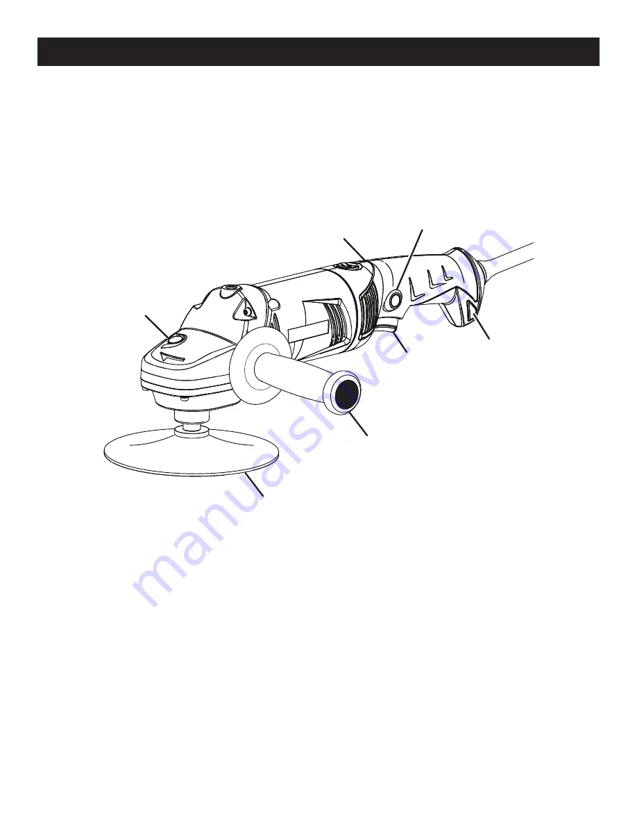
Fig. 1

KNOW YOUR SANDER/POLISHER

See Figure 1.

The safe use of this product requires an understanding of 
the information on the tool and in this operator’s manual 
as well as a knowledge of the project you are attempt-
ing. Before use of this product, familiarize yourself with all 
operating features and safety rules.

SIDE HANDLE

The provided side handle stabilizes your sander/polisher 
and must be used during all operations. The side handle 
can be mounted in three different positions.

LIVE TOOL INDICATOR

The live tool indicator is located on the handle of the 
sander/polisher and indicates that the tool is connected to 
a power supply.

LOCK-ON BUTTON

The lock-on button is convenient for continuous sand-
ing or polishing for extended periods of time. Since the 
sander/polisher has two speeds, the lock-on button can 
lock-on at high or low speed. 

90˚ ROTATING HANDLE

The handle rotates 90˚ to the left or right for ease of use.

SPINDLE LOCK

The spindle lock keeps the spindle from turning while  
installing and removing bonnets and disks.

TWO-SPEED SWITCH TRIGGER

Your sander/polisher is equipped with a two-speed switch 
trigger located in the handle. For low speed, depress the 
trigger halfway. For full speed and power, depress the  
trigger fully.

LOCK-ON

BUTTON

TWO-SPEED 

SWITCH TRIGGER 

SIDE 

 HANDLE

SPINDLE 

LOCK

90˚ ROTATING 

HANDLE

LIVE 

TOOL  

INDICATOR

RUBBER 

DISC

PRODUCT SPECIFICATIONS

Disc Size/Polishing Bonnet ......................................... 6 in.
Speed Switch ........................................................2 Speed
Spindle Size ..................................................... 1/2-20 UNF

Summary of Contents for 315.115060

Page 1: ...00 932 3188 Sears Roebuck and Co 3333 Beverly Rd Hoffman Estates IL 60179 USA Visit the Craftsman web page www sears com craftsman 983000 859 1 03 06 REV 00 Save this manual for future reference WARNING To reduce the risk of injury the user must read and understand the operator s manual before using this product ...

Page 2: ...EARS STORE OR OTHER CRAFTSMAN OUTLET IN THE UNITED STATES FOR FREE REPLACEMENT If this Craftsman tool is used for commercial or rental purposes this warranty applies for only 90 days from the date of purchase This warranty gives you specific legal rights and you may also have other rights which vary from state to state Sears Roebuck and Co Dept 817 WA Hoffman Estates IL 60179 WARRANTY INTRODUCTION...

Page 3: ... your finger on the switch or plugging in tools that have the switch on invites accidents Remove adjusting keys or wrenches before turning the tool on A wrench or a key that is left attached to a rotating part of the tool may result in personal injury Do not overreach Keep proper footing and balance at all times Proper footing and balance enables better control of the tool in unexpected situations...

Page 4: ...kage of parts mounting and any other conditions that may affect its opera tion A guard or other part that is damaged should be properly repaired or replaced by an authorized service center Following this rule will reduce the risk of shock fire or serious injury Make sure your extension cord is in good condition When using an extension cord be sure to use one heavy enough to carry the current your ...

Page 5: ...ator s Manual To reduce the risk of injury user must read and understand operator s manual before using this product Eye Protection Always wear safety goggles or safety glasses with side shields and as necessary a full face shield when operating this product Safety Alert Precautions that involve your safety No Hands Symbol Failure to keep your hands away from the blade will result in serious perso...

Page 6: ... Before beginning power tool operation always wear safety goggles or safety glasses with side shields and when needed a full face shield We recommend Wide Vision Safety Mask for use over eyeglasses or standard safety glasses with side shields Always use eye protection which is marked to comply with ANSI Z87 1 WARNING SAVE THESE INSTRUCTIONS The following signal words and meanings are intended to e...

Page 7: ...eck the power supply EXTENSION CORDS When using a power tool at a considerable distance from a power source be sure to use an extension cord that has the capacity to handle the current the tool will draw An undersized cord will cause a drop in line voltage resulting in overheating and loss of power Use the chart to deter mine the minimum wire size required in an extension cord Only round jacketed ...

Page 8: ...cates that the tool is connected to a power supply LOCK ON BUTTON The lock on button is convenient for continuous sand ing or polishing for extended periods of time Since the sander polisher has two speeds the lock on button can lock on at high or low speed 90 ROTATING HANDLE The handle rotates 90 to the left or right for ease of use SPINDLE LOCK The spindle lock keeps the spindle from turning whi...

Page 9: ... surfaces INSTALLING THE SIDE HANDLE ASSEMBLY See Figure 2 Unplug the sander polisher Insert the handle assembly to the desired operating position Securely tighten by turning the handle assembly clockwise NOTE The side handle must always be used to prevent loss of control and prevent injury Fig 2 TO TIGHTEN TO LOOSEN UNPACKING This product has been shipped completely assembled Carefully remove the...

Page 10: ...e switch trigger is in OFF position before connecting to power supply source LOCK ON BUTTON See Figure 4 This sander polisher is equipped with a lock on feature which is convenient for continuous sanding polishing for extended periods of time To lock on Depress the switch trigger Push in and hold the lock on button located on the side of the handle Release the switch trigger Release the lock on bu...

Page 11: ...he lock depressed rotate the disc clockwise until the spindle clicks into a locked position and will not rotate further To unlock release the spindle lock Fig 6 SPINDLE LOCK INSTALLING REMOVING RUBBER DISC See Figures 6 Unplug the sander polisher Position the tool as shown in figure 6 and lock the spindle lock Thread rubber disc flat face up onto spindle in a clockwise direction Turn until rubber ...

Page 12: ...polisher Remove the sanding disk if necessary Securely retighten spanner nut with the spanner wrench provided if necessary Slip polishing bonnet edges over rubber disc To remove pull polishing bonnet edges over and off rubber disc Fig 8 PULL POLISHING BONNET EDGES OVER DISC TO INSTALL NOTE Some polishes should be buffed while damp while others must be allowed to dry therefore always check the manu...

Page 13: ...vise or use clamps to secure them to a workbench WARNING Unsecured work could be thrown towards the operator causing injury Hold the tool in front and away from you keeping it clear of the workpiece Start the tool by depressing the switch trigger and letting the motor build to its maximum speed Gradually lower sander polisher to the workpiece at a slight 5 to 8 angle Do not attempt to hold the san...

Page 14: ...indings are highly abrasive to bearings brushes commutators etc Consequently we do not recommended using this tool for extended work on these types of materials However if you do work with any of these materials it is extremely important to clean the tool using compressed air LUBRICATION All of the bearings in this tool are lubricated with a sufficient amount of high grade lubricant for the life o...

Page 15: ...ll be found on a plate attached to the motor housing Always mention the model number in all correspondence regarding your SANDER POLISHER or when ordering repair parts Key Part No Number Description Qty 1 300188035 Side handle 1 2 300588002 Rubber Disc 1 3 691206001 Spanner Nut 1 4 630886001 Spanner Wrench 1 5 900593001 Polishing Bonnet 1 983000859 Operator s Manual 3 2 1 5 4 ...

Page 16: ...fessional installation of home appliances and items like garage door openers and water heaters 1 800 4 MY HOME 1 800 469 4663 Call anytime day or night U S A and Canada www sears com www sears ca Our Home For repair of carry in items like vacuums lawn equipment and electronics call or go on line for the location of your nearest Sears Parts Repair Center 1 800 488 1222 Call anytime day or night U S...

Reviews: