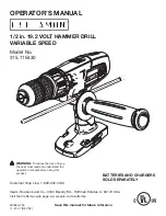
background image

OPERATOR’S MANUAL

Model No.
315.115430

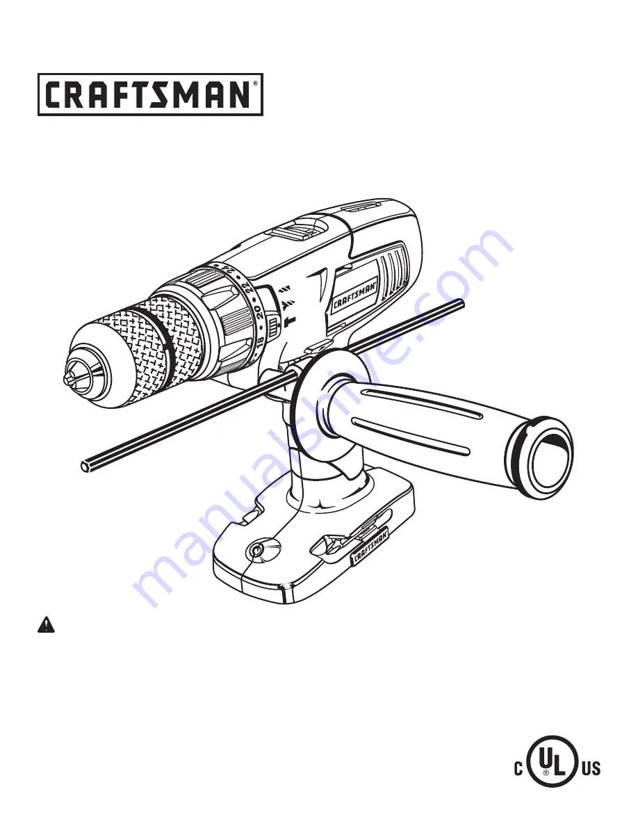
1/2 in. 19.2 VOLT HAMMER DRILL
VARIABLE SPEED

Save this manual for future reference

WARNING: 

To reduce the risk of injury, 

the user must read and understand the 
operator’s manual before using this 
product.

Customer Help Line: 1-800-932-3188

Sears, Roebuck and Co., 3333 Beverly Rd., Hoffman Estates, IL 60179 USA

Visit the Craftsman web page: www.sears.com/craftsman

983000-759
11-21-07 (REV:02)

BATTERIES AND cHARGERS 
SOLD SEPARATELy

Summary of Contents for 315.115430

Page 1: ... To reduce the risk of injury the user must read and understand the operator s manual before using this product Customer Help Line 1 800 932 3188 Sears Roebuck and Co 3333 Beverly Rd Hoffman Estates IL 60179 USA Visit the Craftsman web page www sears com craftsman 983000 759 11 21 07 REV 02 batterIES and chargers sold Separately ...

Page 2: ...used for commercial or rental purposes this warranty applies for only 90 days from the date of purchase This warranty gives you specific legal rights and you may also have other rights which vary from state to state Sears Roebuck and Co Hoffman Estates IL 60179 WARNING Some dust created by power sanding sawing grinding drilling and other construction activities contains chemicals known to cause ca...

Page 3: ...ls that have the switch on invites accidents Remove any adjusting key or wrench before turning the power tool on A wrench or a key left attached to a rotating part of the power tool may result in personal injury Do not overreach Keep proper footing and balance at all times This enables better control of the power tool in unexpected situations Dress properly Do not wear loose clothing or jew elry K...

Page 4: ...immediately with soap and water then neutralize with lemon juice or vinegar If liquid gets into your eyes flush them with clean water for at least 10 minutes then seek immediate medical attention Following this rule will reduce the risk of serious personal injury Save these instructions Refer to them frequently and use them to instruct others who may use this tool If you loan someone this tool loa...

Page 5: ...se in damp locations Read The Operator s Manual To reduce the risk of injury user must read and understand operator s manual before using this product Eye Protection Always wear safety goggles or safety glasses with side shields and as necessary a full face shield when operating this product Safety Alert Precautions that involve your safety No Hands Symbol Failure to keep your hands away from the ...

Page 6: ...e Before beginning power tool operation always wear safety goggles or safety glasses with side shields and when needed a full face shield We recommend Wide Vision Safety Mask for use over eyeglasses or standard safety glasses with side shields Always use eye protection which is marked to comply with ANSI Z87 1 WARNING SERVICE Servicing requires extreme care and knowledge and should be performed on...

Page 7: ...r Speed 0 5 200 0 18 200 BPM Clutch 24 Position Torque 420 in lb Blows Per Minute Fig 1 KEYLESS CHUCK LEVEL SCREWDRIVER BITS TWO SPEED GEAR TRAIN HI LO SWITCH TRIGGER AUXILIARY HANDLE ASSEMBLY DIRECTION OF ROTATION SELECTOR FORWARD REVERSE CENTER LOCK REAR VIEW TORQUE ADJUSTMENT RING LEVEL BIT STORAGE DEPTH STOP ROD QUICK MODE SELECTOR ...

Page 8: ...tion of rotation forward reverse center lock selector located above the switch trigger for changing the direction of bit rotation Setting the switch trigger in the OFF center lock position helps reduce the possibility of accidental starting when not in use KEYLESS CHUCK The keyless chuck allows you to hand tighten or release the drill bit in the chuck jaws LEVELS Levels are located on the top and ...

Page 9: ...Insert end of depth stop rod into depth stop rod slot on the back of the plate ASSEMBLY UNPACKING This product requires assembly n Carefully remove the tool and any accessories from the box Make sure that all items listed in the packing list are included n Inspect the tool carefully to make sure no breakage or damage occurred during shipping n Do not discard the packing material until you have car...

Page 10: ...aftsman 19 2 V nickel cadmium battery packs For complete charging instructions refer to the Operator s Manual for the battery packs and chargers listed in the General Safety Rules TO INSTALL BATTERY PACK See Figure 3 Lock the switch trigger by placing the direction of rotation selector in the center position Place battery pack in the tool Align raised rib on battery pack with groove inside tool Ma...

Page 11: ... controlled by a selector located above the switch trigger With the drill held in normal operating position the direction of rotation selector should be positioned to the left of the switch trigger for drilling The drilling direction is reversed when the selector is to the right of the switch trigger Setting the switch trigger in the OFF center lock position helps reduce the possibility of acciden...

Page 12: ... BODY DRILL BIT UNLOCK RELEASE CHUCK JAWS LOCK TIGHTEN CHUCK COLLAR TWO SPEED GEAR TRAIN HI LO HI SPEED LO SPEED Fig 7 2 1 KEYLESS CHUCK See Figure 6 The drill has a keyless chuck to tighten or release drill bits in the chuck jaws Grasp and hold the collar of the chuck with one hand Rotate the chuck body with your other hand The arrows on the chuck indicate which direction to rotate the chuck body...

Page 13: ...re are twenty four torque indicator settings located on the front of the drill Rotate the adjusting ring to the desired setting 1 4 For driving small screws 5 8 For driving screws into soft material 9 12 For driving screws into soft and hard materials 13 16 For driving screws into hard wood 17 24 For driving large screws TO DECREASE TORQUE HAMMER MODE DRILL MODE TO INCREASE TORQUE MODE SELECTOR sc...

Page 14: ...l resulting in possible serious personal injury or damage to the chuck Rotate the chuck clockwise to tighten the chuck jaws securely on the bit Note Rotate the chuck body in the direction of the arrow marked LOCK to tighten the chuck jaws Do not use a wrench to tighten or loosen the chuck jaws Fig 11 INSTALLING BITS See Figures 10 11 Lock the switch trigger by placing the direction of rotation sel...

Page 15: ...on the depth gauge clamp Adjust the depth stop rod so that the drill bit extends beyond the end of the rod to the required drilling depth When drilling holes with the depth stop rod installed the desired hole depth has been reached when the end of the rod comes in contact with the surface of the workpiece ADJUSTING THE AUXILIARY HANDLE ASSEMBLY See Figure 13 Loosen the auxiliary handle assembly by...

Page 16: ...us ing to help keep the drill bit level during use Check the direction of rotation selector for the correct setting forward or reverse Secure the material to be drilled in a vise or with clamps to keep it from turning as the drill bit rotates Hold the drill firmly and place the bit at the point to be drilled Depress the switch trigger to start the drill Move the drill bit into the workpiece applyi...

Page 17: ...eed steel bits for metal or steel drilling Select normal drilling mode Begin drilling at a very low speed to prevent the bit from slipping off the starting point Maintain a speed and pressure which allows cutting without overheating the bit Applying too much pres sure will Overheat the drill Wear the bearings Bend or burn bits and Produce off center or irregular shaped holes When drilling large ho...

Page 18: ...cling and or disposal options WARNING Upon removal cover the battery pack s terminals with heavy duty adhesive tape Do not attempt to destroy or disassemble battery pack or remove any of its components Lithium ion and nickel cadmium batteries must be recycled or disposed of properly Also never touch both termi nals with metal objects and or body parts as short circuit may result Keep away from chi...

Page 19: ...ck and tighten the chuck jaws securely Tap sharply with a mallet in a counter clockwise direction This will loosen the chuck on the spindle It can now be unscrewed by hand TO RETIGHTEN A LOOSE CHUCK The chuck may become loose on the spindle and develop a wobble Also the chuck screw may become loose causing the chuck jaws to bind and prevent them from closing To tighten Lock the switch trigger by p...

Page 20: ...n ordering repair parts SEE BACK PAGE FOR PARTS ORDERING INSTRUCTIONS PARTS LIST Key Part No Number Description Qty 1 6613401 Chuck Screw 1 2 690033058 Chuck 1 3 940237091 Data Plate 1 4 940114128 Logo Plate 1 5 300188033 Auxiliary Handle Assembly 1 6 6341203 Depth Stop Rod 1 983000759 Operator s Manual 1 2 3 4 5 6 CRAFTSMAN 19 2V CORDLESS HAMMER DRILL 315 115430 ...

Reviews: