background image

Summary of Contents for 315.117131

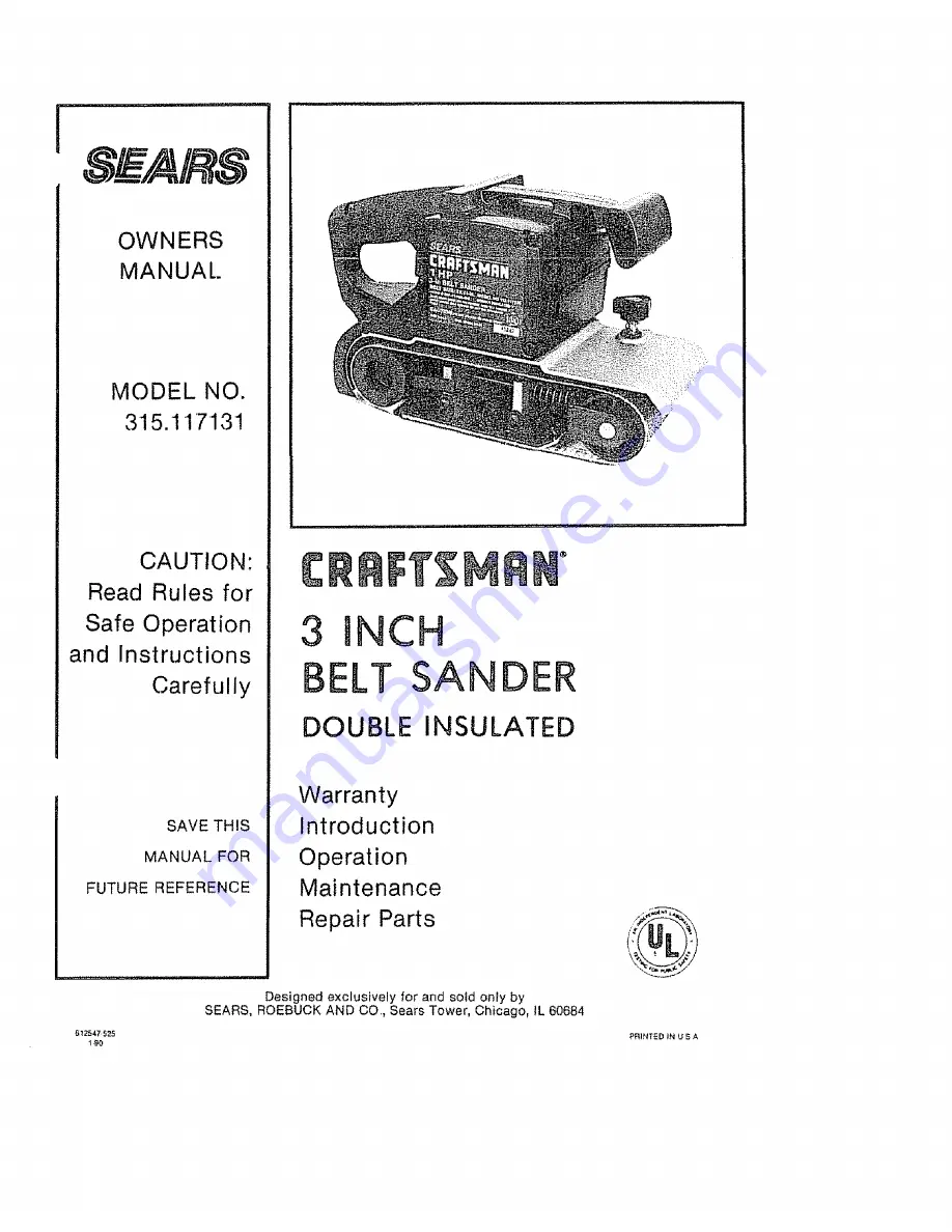
Page 1: ...ion and Instructions Carefully SAVE THIS MANUAL FOR FUTURE REFERENCE 3 DOUBLE SANDER INSULATED Warranty Introduction Operation Maintenance Repair Parts Designed exclusively for and sold only by SEARS ROEBUCK AND CO Sears Tower Chicago lL 60684 6_2_47 525 PRINTED IN U S A 1 _J0 ...

Page 2: ...ch eliminates the need for the usual three wire grounded power cord and grounded supp ly system Wherever there ts electric current _nthe too there are two complete sets of insulation to pro tect the user Alt exposed metal parts are isolated from the tnternat metal motor components with pro tecttng insulation RULES FOR SAFE OPERATION READ ALL INSTRUCTIONS 1 KNOW YOUR POWER TOOL Read owner s manual ...

Page 3: ...comply can result in electrical shock causing serious injury or worse 21 KEEP HANDS AND FINGERS AWAY FROM SANDING AREA AND MOVING SANDING BELT 22 NEVER USE IN AN EXPLOSIVE ATMOSPHERE Normal sparking of the motor could ignite fumes 23 INSPECT TOOL CORDS PERIODICALLY and if damaged have repaired at your nearest Sears Repair Center Stay constantly aware of cord location 24 INSPECT EXTENSION CORDS PER...

Page 4: ...ave the Lock On feature engaged during use and your Sander becomes disconnected from power supply disengage the Lock On feature immediatel PREPARING FOR OPERATION For ease of operation and maintaining proper con trot your Sander has a front handle and a rear han die These handles allow two hand operation which aid in maintaining controi keeping sanding area level with workpiece and keeping hands c...

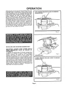
Page 5: ...g with each grit belt until the surface is uniform INSTALLING AND ADJUSTING SANDING BELT DISCONNECT SANDER FROM POWER SUPPLY WHILE ASSEMBLING PARTS OR MAKING AD JUSTMENTS To release the sanding belt lift tenslon release lever straight up as shown in f_gure 4 When sufficient force is exerted the spring wilt be compressed allowing the pulley to lock in a rear position This frees the sanding belt so ...

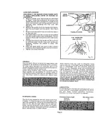
Page 6: ...the outer edge of the base of your Sander ell life wilt be greatly increased if a few seconds are spent adjusting the belt tracking Before placing Sander on work surfac squeeze the trigger switch and let the motor reach its maximum speed then toweryour Sander to the work surface with a slight forwardmotion Using the rear handle to control your Sander and the front han dle only to guide it move it ...

Page 7: ...VER tN PLACE SWITCH REPLACEMENT DISCONNECT THE SANDER FROM POWER SUPP LY WHILE REPLACING PARTS OR MAKING AD JUSTMENTS t Remove the handle cover and screws NOTETHE LOCATIONS OF ALL WIRING IN THE HANDLE AND HOW EACH CONNECTION IS MADE TO THE SWITCH Connections and wiring position must be identical when installing the new switch See Figure I2 Lift the switch away from the handle then release the lead...

Page 8: ...plastics are susceptible to various types of commerciaI solvents and may be damaged by their use Use clean cieths to remove dirt carbon dust etc EXTENSION CORDS The use of any extension cord witl cause some loss of power To keep the loss to a minimum and to pro vent too overheating follow the recommended cord sizes on the chart at right When too_ s used out doors use only extension cords suitable ...

Page 9: ... Coarse CRRF r_MRN cat No 9_ 22305 X Coarse Dustless Sanding Attachment 9 11766 The use of attachments or accessories not listed above might be hazardous i i i i The operation of any Sander can result in foreign objects being thrown into your eyes which can result in severe eye damage Before commencing power tool operation always wear safety goggles or safety glasses with side shields and a full f...

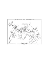
Page 10: ...2 CRAFTSMAN 3 INCH BELT SANDER MODEL NUMBER 315 117131 SEE NOTE W PAGE 11 11 15 34 35 13 31 32 12 3O 42 17 ill For Parts List See Page 11 Page 10 ...

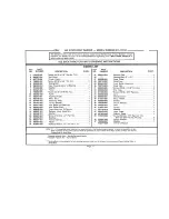
Page 11: ...r 44 Screw 10 32 x 1 2 Pan Hd 1 45 Bushing 2 Torsion Spring 1 46 Platen 1 47 Screw 10 32 x 1 2 Pan Hd T F 2 PART NUMBER DESCRIPTION QUAN 998378 001 998380 001 99811_001 999942 001 703774 003 98959_001 999932 001 817966 009 990493 006 999929 001 613651 001 998895 001 706239 845 998358 001 616247 001 931744 818 999463 001 967878 003 612665 006 622347 003 705239 847 612547 525 Backing Pad 1 Sanding B...

Page 12: ...r visiL The model number of your Belt Sander will be found on the plate located on the side of your sander WHEN ORDERING REPAIR PARTS ALWAYS GIVE THE FOLLOWING INFORMATION PART NUMBER MODEL NUMBER 315 117131 PART DESCRIPTION o NAME OF ITEM 3 Belt Sander Alt parts listed may be ordered from any Sears Ser vice Center and most Sears stores If the parts you need are not stocked locally your order will...

Reviews: