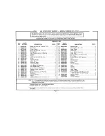
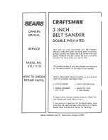
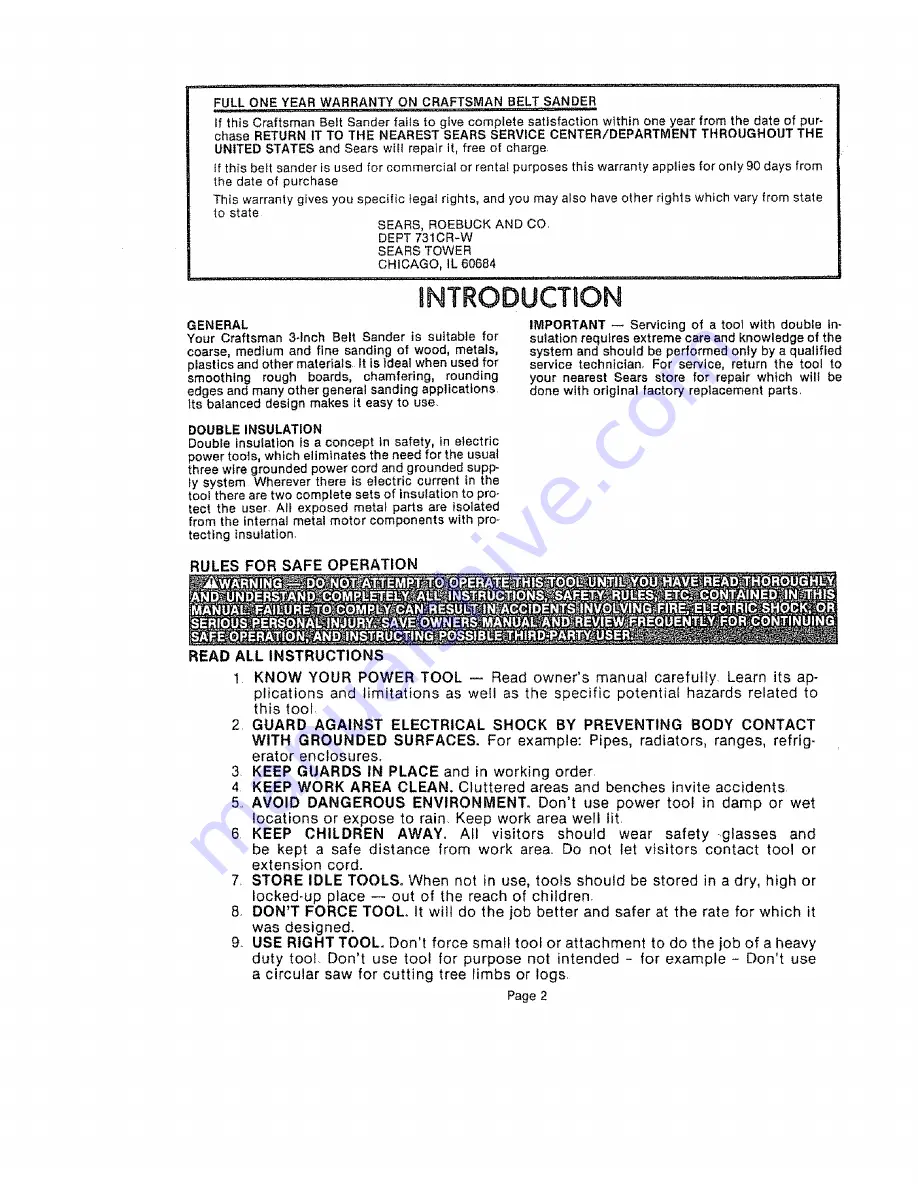
Craftsman 315.117131, Owner'S Manual
The Craftsman 315.117131 is a versatile tool that is perfect for all your DIY projects. To get the most out of your tool, make sure to download the free owner's manual from 88.208.23.73:8080. This comprehensive manual includes step-by-step instructions and useful tips to help you master this tool.
Share
Download


Reviews:
No comments
Related manuals for 315.117131

All-U-Need Glass/Crystal
Brand: Hi-Tech Diamond Pages: 16
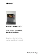
Sinorix al-deco STD
Brand: Siemens Pages: 32

ProLINE-RoadRunner
Brand: Siemens Pages: 58

WS 400-30
Brand: Siemens Pages: 60

21260- 0209
Brand: Luna Pages: 92

MM3156A
Brand: BURT Pages: 28

409 483
Brand: Berner Pages: 159

180723
Brand: Berner Pages: 163

275647
Brand: Parkside Pages: 66

275679
Brand: Parkside Pages: 76

47123
Brand: Parkside Pages: 29

5 IN. BRUSHLESS RANDOM ORBIT SANDER
Brand: Kobalt Pages: 28

Xq 270
Brand: Parkside Pages: 55

TTA-11241
Brand: Taurus Pages: 24

3745
Brand: Skil Pages: 128

SV 12SF
Brand: Hitachi Koki Pages: 41

RS2**A-***
Brand: ARO Pages: 8

GE 5
Brand: Flex Pages: 302


