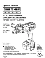
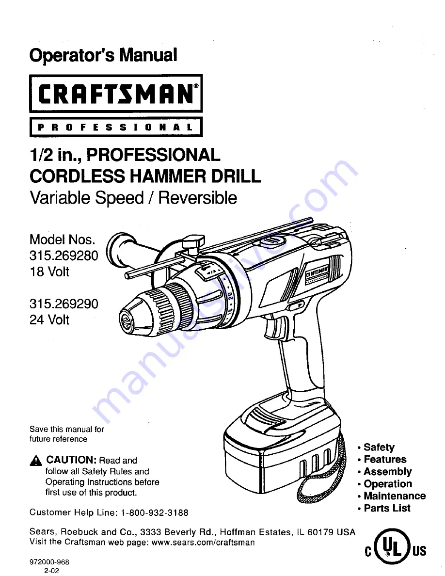
background image

Summary of Contents for 315.269280

Page 1: ...is manual for future reference CAUTION Read and follow all Safety Rules and Operating Instructions before first use of this product Customer Help Line 1 800 932 3188 Safety Features Assembly Operation Maintenance Parts List Sears Roebuck and Co 3333 Beverly Rd Hoffman Estates IL 60179 USA Visit the Craftsman web page www sears com craftsman 972000 968 2 02 0 s ...

Page 2: ...state Sears Roebuck and Co Dept 817 WA Hoffman Estates IL 60179 _b Look for this symbol to point out important safety precautions It means attention Your safety is involved _ WARNING The operation of any power tool _an result in foreign objects being thrown into your eyes which can result in severe eye damage Before beginning power tool operation always wear safety goggles or safety glasses with s...

Page 3: ...ry A charger that may be suitable for one type of battery may create a risk of fire when used with another battery Use battery only with charger listed MODEL BA rFERY PACK CHARGING 315 269280 ITEM NO 9 11034 ITEM NO 9 11040 981404 001 981399 001 315 269290 ITEM NO 9 11035 ITEM NO 9 11040 981405 001 981399 001 Use battery operated tool only with specifically designated battery pack Use of any other...

Page 4: ...on where the cutting tool may contact hidden wiring Contact with a live wire will make exposed metal parts of the tool live and shock the operator Additional Rules For Safe Operation Know your power tool Read operator s manual carefully Learn its applications and limitations as well as the specific potential hazards related to this tool Following this rule will reduce the risk of electric shock fi...

Page 5: ...elow Cord Length Feet 25 50 100 Cord Size AWG 16 16 16 Note AWG American Wire Gage Do not operate charger with a damaged cord or plug If damaged have replaced immediately by a qualified serviceman Followingthis rule will reduce the riskof electric shock firs or serious personal injury Do not operate charger if it has received a sharp blow been dropped or otherwise damaged in any way take it to a q...

Page 6: ...l attention and understanding The safety warnings do not by themselves eliminate any danger The instructions or warnings they give are not substitutes for proper accident prevention measures SYMBOL MEANING A SAFETY ALERT SYMBOL Indicates danger warning or caution May be used in conjunctionwith other symbols or pictographs DANGER Failure to obey a safety warning will result in serious injury to you...

Page 7: ...arting when not in use VARIABLE SPEED This tool has a variable speed switch that delivers higher speed with increased trigger pressure Speed is controlled by the amount of switch trigger depression TWO SPEED GEAR TRAIN Your hammer drill has a two speed gear train designed for drilling or driving at HI or LO speeds A slide switch is located on top of your drill to select either HI or LO speed 7 FOR...

Page 8: ...INGSCREW TWOSPEED GEARTRAIN HI LO LEVEL GAGEROD BIT STORAGE AREA KEYLESS CHUCK MODE SELECTOR TORQUE ADJUSTMENT RING TRIGGER DIRECTIONOF ROTATION SELECTOR FORWARD REVERSE BA R ERY PACK SCREWDRIVER BITS _NRIST STRAP Fig 1 ...

Page 9: ...LIGHT ON INDICATESFULLY CHARGEDANDSLOWCHARGING TO MAINTAINBA FrERYPACK CHARGER BATrERY PACKSHOWN INCHARGER Fig 2 CHARGER See Figure 3 Your charger has a key hole hanging feature for convenient space saving storage Screws should be installed so that center distances are 4 1 8 inches apart 4 1 8 in BACKSIDEOF CHARGER Fig 3 9 ...

Page 10: ... prevent possible loss of control auxiliary handle should be checked periodically for tightness Do not operate hammer drill with auxiliary handle loose TO ATTACH BATTERY PACK TO DRILL See Figure5 Note Battery pack isshippedin a lowchargecondition Therefore it must be chargedprior touse Refertopage 12 CHARGING BATFERY PACK for charging instructions Lock the switch trigger by placing the direction o...

Page 11: ...the switch trigger by placing the direction of rotation selector in center position See Figure f3 Loosen the chuck jaws from drill bit To loosen grasp and hold the drill with one hand while rotating chuck sleeve with your other hand Note Rotate chuck sleeve in the direction of the arrow marked UNLOCK to loosen the chuck jaws Do not use a wrench to tighten or loosen the chuck jaws Remove drill bit ...

Page 12: ...ck becomes fully charged the red light will tum OFF and the green light will tum ON After normal usage 1 hour of charging time is required to be fully charged A minimum charge time of 1 1 2 hours is required to recharge a completely discha_ed tool The battery pack will become slightly warm to the touch while charging This is normal and does not indicate a problem Do not place charger in an area of...

Page 13: ...st drilling or driving applications TWOSPEED GEARTRAIN HI LO LO SWITCH LOCK See Figure 13 The switch trigger can be locked in the OFF position This feature can be used to prevent the possibility of accidental starting when not in use To lock switch trigger place the direction of rotation selector in center position SELECTOR REVERSE FORWARD Fig 13 A WARNING Battery tools are always in operating con...

Page 14: ...LE TORQUE CLUTCH Your drill is equipped with an adjustable torque clut h for driving different types of screws into different materials The proper setting depends on the type of material and the size of screw you are using TO ADJUST TORQUE Identify the twenty four torque indicator settings located on the front of your drill See Figure 15 Rotate adjusting ring to the desired setting 1 4 For driving...

Page 15: ...drill at a low speed until the hole is started The material to be drilled should be secured in a vise or with clamps to keep it from turning as the drill bit rotates Hold tool firmly and place the bit at the point to be drilled Depress the switch trigger to start tool Move the drill bit into the workpiece applying only enough pressure to keep the bit cutting Do not force or apply side pressure to ...

Page 16: ...ed edges on the back side of the hole Do not lock the trigger on for jobs where your hammer drill may need to be stopped suddenly METAL DRILLING For maximum performance use high speed steel bits for metal or steel drilling Turn mode selector on hammer drill to normal drilling action Begin drilling at a very low speed to prevent the bit from slipping off the starting point Maintain a speed and pres...

Page 17: ... left hand threads SCREWDRIVER Fig 21 Insert hex key in chuck and tighten chuck jaws securely Tap sharply with a mallet in a counterclock wise direction This will loosen chuck on the spindle It can now be unscrewed by hand Gee Figure 22 MALLET Fig 22 TO RETIGHTEN A LOOSE CHUCK Periodically check chuck screw for tightness A loose chuck screw may cause the chuck jaws to bind and prevent them from cl...

Page 18: ...btain the longest possible battery life we suggest the following Store and charge your batteries in a cool area Temperatures above or below normal room temperature will shorten battery life Never store batteries in a discharged condition Recharge them immediately after they are discharged All batteries gradually lose their charge The higher the temperature the quicker they lose their charge If you...

Page 19: ...19 ...

Page 20: ...en ordering repair parts SEE BACK PAGE FOR PARTS ORDERING INSTRUCTIONS I 1 7 2 3 5 6 Key Pa_ No Number 1 975379 000 2 982391 001 3 975111 001 4 981501 001 5 _11034 6 980199 000 7 9 11040 8 981500 001 972000 968 PARTS LIST Description Quan Screw Special 1 Auxiliary Handle Assembly 1 1 2 in Chuck Item No 9 20956 1 Logo Plate 1 Battery Pack 981404 001 1 Depth Gage Rod 1 Charger 981399 001 1 Carrying ...

Page 21: ...ering repair parts SEE BACK PAGE FOR PARTS ORDERING INSTRUCTIONS I 3 2 7 4 5 6 Q Key Pa_ No Number 1 975379 000 2 982391 001 3 975111 001 4 981501 001 5 _ 11035 6 980199 000 7 _11040 8 981499 001 972000 968 PARTS LIST Description Quan Screw Special 1 Auxiliary Handle Assembly 1 1 2 in Chuck Item No 9 20956 1 Logo Plate 1 Battery Pack 981405 001 1 Depth Gage Rod 1 Battery Charger 981399 001 1 Carry...

Page 22: ...air Center 1 800 488 1222 Anytime day or night www sears com For the replacement parts accessories and owner s manuals that you need to do it yourself call Sears PartsDirect sM 1 800 366 PART 6 a m 11 p m CST 1 800 366 7278 7 days a week www sears corn partsdirect To purchase or inquireabout a Sears Service Agreement 1 800 827 6655 7 a m 5 p m CST Men Sat SEARS TM Registered Trademark Trademark of...

Page 23: ...l para referencia futura A ATENCION Lea cuidadosamente todas las Reglasde Seguridady las Instrucciones antesde usaresta herramienta Nn de tel6fono de ayuda a los clientes 1 800 932 3188 Seguridad Caracter sticas Montaje Funcionamiento Mantenimiento Lista de Repuestos Sears Roebuck and Co 3333 Beverly Rd Hotfman Estates IL 60179 USA Visita la pbgina Web de Craftsman www sears com craftsman 972000 9...

Page 24: ... Co Dept 817WA Hoffman Estates IL 60179 _ Este simbolo le indica importantes reglas de seguridad iSignifica atenci6n Existe riesgo para su seguridad ADVERTENCIA La utilizaci6n de cualquier herramienta mec nica puede causar la proyecci6n de objetos extrafios a sus ojos Io cual puede ocasionar dafios oculares severos Antes de comenzar a usar la herramienta mec nica siempre use sus lentes protectores...

Page 25: ...o de bateda puede crear un peligro de incendiocuando se usa con otra bateda Use la bateda correspondienteal cargador que se indica MODELO BLOQUE DE BATERIAS CARGADOR 315 269280 Art No 9 11034 Art No 9 11040 981404 001 981399 001 MODELO BLOQUE DE BATERIAS CARGADOR 315 269290 Art No 9 11035 Art No 9 11040 981405 001 981399 001 Use la herramienta a baterla solamente con el bloque de baterlas especl f...

Page 26: ...metal expuestas de la herramienta tambi_n quedardn bajo tensi6n y producir n un choque el_ctrico para el operador Reglas Adicionales para Funcionamiento Seguro Conozca su herramienta mec_inica Lea cuidadoeamente el manual del usuario Aprenda sue aplicaclones y limltaciones as como tambidn los riesgos potenclales especfflcos relacionados con esta herramienta Si se cumple esta reg a se reducirb el d...

Page 27: ...n Pies 25 50 100 Tamafio del Cordbn AWG 16 16 16 Nots AWG American Wire Gage No haga funcionar el cargador si el cordbn o el enchufe est_tndahados Si estdn daftados hdgalos reemplazar inmediatamente por un electricista calificado Si se cumple esta regis se reducir_ el riesgo de un choque el_ctrico incendioo lesibn personalgrave No haga funcionar el cargador si ha recibido un golpe fuerte si se ha ...

Page 28: ... y las expllcaclones que acompanan estos s mbolos merecen culdadosa atenci6n y comprensi6n Las advertenclas por si mlsmas no eliminan nlngdn peligro Las instrucclones o las advertencias que se proporclonan no reemplazan a las medldas adecuadas de prevenclbn de accidentes SIMBOLO SIGNIFICADO A SIMBOLO DE ALEFrrA SOBRE SEGURIDAD Indica atencibn advertenciao peligro Puede usarse conjuntamentecon otro...

Page 29: ... interruptorde velocidadvariable que proporcionavelocidad y torsi6n mils altas cuandose aumenta la presi6nen el gati lo La velocidad es controladapor la cantidad de presi6n que se ejerza en el gatillo TREN DE ENGRANAJES DE DOS VELOCIDADES Su taladro martillotiene untren de engranajes de dos velocidadesdisehado para taladrar o atornillara velocidad ALTA HI o BAJA LO SELECTOR DE MARCHA ADELANTE RETR...

Page 30: ...ALTA BAJA TORNILLO DE ALETAS NIVEL VARILLADE CALIBREDE PROFUNDIDAD GUARDARBROCAS PORTABROCA SINLLAVE SELECTOR DE MODO SELECTORDE DIRECCION DE ROTACION MARCHAADELANT_ RETROCESO ANILLOSELECTOR BLOQUEDE BATERIAS PUNTASDE DESTORNILLADOR CORREAPARA LAMUNECA Fig 1 8 ...

Page 31: ...NDICA TOTALMENTECARGADOY MODODE CARGALENTAPARAMANTENEREL BLOQUEDEBATERIAS BLOQUEDE BATERIAS INSTALADO EN ELCARGADOR Fig 2 CARGADOR YerFigura 3 Su cargador est provisto de dos bocallaves en la parte trasera para facilitarsu almacenamiento colg_ ndolo de manera apropiada Se deben instalar dos tornillosde modo que la distancia de centro a centro sea de 4 1 8 pulgadas 4 1 8 pulg PARTETRASERA DELCARGAD...

Page 32: ...ja auxiliar debe ser revisada peri6dicamente para verificar si est bien apretada No haga funclonar el taladro martlllo con la manlJaauxlllar suelta INSTALACION DEL BLOQUE DE BATERIAS EN EL TALADRO Ver Figura 5 Nota El bloque de baterias ha sidoenviado con carga baja Por Iotanto debe cargarseantes de su uso Consultela P gina12 CARGA DEL BLOQUE DE BATERIAS para las instrucciones de carga Bloquee el ...

Page 33: ...3 Afloje las mordazas del portabroca Para aflojar sujete y sostanga el taladro con una mano a a vez que gira el manguito del portabrocacon la otra mano Nota Gire el manguito del portabroca en la direccibn de la flecha marcada UNLOCK Aflojar para aflojar las mordazas del portabroca No use una Ilave para apretar o aflojar las mordazas del portabroca Retire la broca de las mordazas USO DE LA VARILLA ...

Page 34: ...rcano para su revision o reemplazo Cuando el bloque de baterias est0 totalmente cargado la luz roja se APAGARA y se ENCENDERA la luz verde Despu0s de uso normal se requiere una 1 hora de carga para que el bloque de baterfas quede totalmente cargado Se requiere un minimo tiempo de carga de 1 1 2 horas para recargar una herramienta que est0 completamente descargada El bloque de baterias permanecerd ...

Page 35: ...r_pido o instalaci6n r_pida de tornillos TREN DEENGRANAJES DE DOSVELOCIDADES HI LO ALTA BAJA BAJA VELOCIDAD BLOQUEO DEL GATILLO Ver Figure 13 El gatillode su taladro puede ser bloqueado en la posicibn APAGADO OFF Esta caractedstica puede usarse para evitar la posibilidadde la puesta en marcha accidental cuando no est en uso Para bloquearetgatillo coloque el selector de rotacibnde direccibnen la po...

Page 36: ...talar diversos tipos de tornillos en distintos materiales El ajuste adecuado depende del tipo de material y del tamaho de tornillo que este usando AJUSTE DE LA TORSION Identifique losveinticuatroajustes del indicadorde torsibn situadoen la parte delantera de su taladro VerFigura 15 Gire el anillo selector al ajustedeseado 1 4 Parainstalar tornillospequeSos 5 8 Parainstalar tornillosen material bla...

Page 37: ...ga funcionar el taladro a baja velocidad hasta que el agujero sea comenzado Sujete el material que va ser taladrado en un tornillo de banco o con mordazas para evitar que gire cuando la broca del taladro est girando Sujete firmemente el taladro y coloque la broca en el punto que va ser taladrado Oprima el gatillo para poner en marcha el taladro Mueva la broca en el trabajo aplicando solamente sufi...

Page 38: ...rte posterior del agujero No utilice el bloqueo en marcha del gatillo en trabajos en que puede necesitar tener que apagar el taladro repentinamente TALADRADO EN METAL Para un m ximo rendimiento use brocas de acero de alta velocidad para taladrado en metal o acero Gire el anilto selector de modo del taladro martillo hacia taladrado normal Comience a taladrar a velocidad muy baja para evitar que la ...

Page 39: ... Fig 21 Inserte la Ilave hexagonal en el portabroca y apriete firmemente las mordazas Golpee la Ilave hexagonal con un mazo en direcci6n a la izquierda Esto aflojar_ el portabroca en el husillo Despu_s puede ser destornillado a mane Yef F gufa 22 MAZO Fig 22 PARA APRETAR UN PORTABROCA SUELTO Revise peri6dicamente la torsibn del torniltodet portabroca Un tornillo suelto puede causar que las mordaza...

Page 40: ...Io siguiente Guarde y cargue las baterias en un lugar fresco Las temperaturas superiores a la temperatura ambiente normal acortar_ n la vida _til de las baterias Nunca guarde las baterias descargadas C_ rguelas inmediatamente despu_s que se han descargado Todas las bateHas pierden gradualmente su carga Mientras m s alta es la temperatura m s r_ pidamente pierden ta carga Si guarda su herramienta p...

Page 41: ...19 ...

Page 42: ... LA ULTIMA PAGINA PARA LAS INSTRUCCIONES COMO PEDIR REPUESTOS I 7 2 3 Q 6 No de Ref 1 2 3 4 5 6 7 8 Numero de Repuesto 975379 000 982391 001 975111 001 981501 001 911034 980199 000 _11040 981500 001 972000 968 LISTA DE REPUESTOS Descripcibn Cant Tornillo Especial 1 Conjunto de Manija Auxiliar 1 Portabroca de 1 2 pulg Articulo No 9 20956 1 Placa de Logo 1 Bloque de Baterias 981404 001 1 Varilla de ...

Page 43: ...s VER LA ULTIMA PAGINA PARA LAS INSTRUCCIONES COMO PEDIR REPUESTOS 1 7 2 3 Q 6 No de Ref 1 2 3 4 5 6 7 8 Ndmero de Repuesto 975379 000 982391 001 975111 001 981501 001 911035 980199 000 911040 981499 001 972000 968 LISTA DE REPUESTOS Deecripci6n Cant Tornillo Especial 1 Conjunto de Manija Auxiliar 1 Portabroca de 1 2 pulg Art culo No 9 20956 1 Placa de Logo 1 Bloque de Baterias 981405 001 1 Varill...

Page 44: ...s and owner s manuals that you _eed to do it yourself call Sears PartsDirect SM 1 80 0 366 PART 6a m p m CST 1 800 366 7278 7 days a week _m_tLsears com partsdirect To purchase or inquire about a Sears Service Agreement 1 800 827 6655 7a m 5 p m CST Mon Sat _ f Para pedir servicio de reparaciSn a domicilio Au Canada pour service en fran_ ais I SEARS 1 HomeCentrar y para ordenar piezas con entrega ...

Reviews: