background image

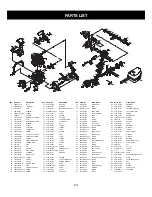
PARTS LIST

Item

1

2

3

4

5

6

7

8

9

10

11

12

13

14

15

16

17

18

19

20

21

22

23

24

25

26

27

28

29

30

31

32

33

Parts No.

9NAB-5/16-24

9228-31B206

9157-310201

9DB-620201

9SREB-10/24-2.75

9WFB-0.2

9072-310201F

9221-310001

9228-310203F

9155-310201

9076-310201

9228-310208

9154-310201

9SKKBY8/16-0.5

9124-310201

9072-310202F

9014-310212

9036-310201

9059-310201

9CA-0.46

9PC-10-32.5

9290-310201

9189-310201

9292-310201F

9295-320001

9SKKBY10/24-0.62

9014-310203

9131-310202

9288-310201-CH

9191-310201

9051-310202

9SKKBY10/24-0.75

9STDZY10/24-2.79

Description

NUT

FLYWHEEL

SEAL

BEARING

SCREW

WASHER

CRANKCASE LOWER

KEY

C'SHAFT/C'ROD ASS'Y

BEARING

O RING

PUMP ASS'Y

CONNECTOR

SCREW

FITTING, PULSE LINE

CRANKCASE UPPER

GASKET

CLAMP, WIRE HOSE

CONDUIT, FLEX

RING

PIN

PISTON

RING, PISTON

CYLINDER

SPARK PLUG

SCREW

FLANGE

EYELET

IGNITION ASS'Y

STUD

CONTACT, CROUNT

SCREW

SCREW

Item

34

35

36

37

38

39

40

41

42

43

44

45

46

47

48

49

50

51

52

53

54

55

56

57

58

59

60

61

62

63

64

65

66

Parts No.

9014-310208

9082-310201

9228-310217

9SKKBY10/24-0.5

9211-310201

9183-310201

9082-310205

9017-310204

9158-310201

9NAC-10/24

9131-310203

9014-310204

9102-310202

9014-310202

9124-310203

9287-310201

9014-310201

9131-310204

9024-310202

9124-310204

9SREB-10/24-1.625

9228-31B208

9SKKBY10/14-0.625

9WFZ-0.18

9223-310201

9183-310202

9228-310205

9142-310002

9129-310214

9SKKBY10/24-1

9043-310201

9124-310206

9228-310206

Description

WASHER

BAFFLER

MUFFLER BODY ASS'Y

SCREW

PLATE

SCREEN

BAFFLER

COVER, MUFFLER

LOCKPLATE

NUT

EYELET

FLANGE

PLATE

GASKET

BOOT

CARB

FLANGE

EYELET

SPRING

BOOT

SCREW

STARTER ASS'Y

SCREW

WASHER

SCREEN

FUEL/OIL TANK ASS'Y

PRIMER, REMOTE

HOSE 

SCREW

PLATE

SPACE

CAP, FUEL

Item

67

68

69

70

71

72

73

74

75

76

77

78

79

80

81

82

83

84

85

86

87

88

89

90

91

92

93

94

95

96

97

98

99

Parts No.

9182-310001

9129-310004

9SKKZY10/14-01

9124-310202

9070-310002

9129-310209

9013-310201

9252-310002

9131-310206

9043-310203

9043-310202

9SKKBY6/19-0.375

9SJKB-12/14-1.5

9228-31B202

9228-310216

9SKKBY10/14-02

9SKKBY10/14-0.68

9228-310204

9067-310202

9214-310101

9228-310230

9114-310202

9013-310202

9228-310213

9228-310214

9228-310232

9SKKBY8/16-0.625

9SKKBY-8/16-1

9010-310203

9228-310222

9WFB-4.9-17

9024-310206

9010-310201

Description

FILTER, FUEL

HOSE 

SCREW

BOOT, CARB

VALVE DUCKBILL

HOSE 

PLUG    

FILTER

WASHER

PLATE, BAR

PLATE, FLANGE

SCREW

SCREW

HANDLE ASS'Y

COVER ASS'Y

SCREW

SCREW

AIR CLEANER ASS'Y

COVER

SCREW

CHOKE ASS'Y

ROD, CHOKE

PLUG

ISOLATOR ASS'Y

CABLE ASS'Y

COVER ASS'Y, HANDLE

SCREW

SCREW

WIRE

ISOLATOR ASS'Y

WASHER

SPRING

CABLE

14 57

58

59

65

64

68

66

62

61

79

76

77

78

123

122

121

120

86

85

84

83

82

81

117

106

69

91

90

87

72
71

71

74

89

88

60

73

63

75

124

105

103

104

102

99

100

101

98

97

14

91

96

95

94

93

14

1

2

5

6

7

4

3

110

11

15

112

113

114

115

18

19

23

25

29

31

32

39

40

41

42

43

33

35

28

27

26

3

4

8

9

21

20

13

10

70

44

45

47

50

52

53

54

6

51

48

36

37

108

14

111

22

16

34

116

17

38

46

49

12

92

69

67

24

125

107

30

55

80

63

65

109

118

119

56

126

127

128

24

Item

100

101

102

103

104

105

106

107

108

109

110

111

112

113

114

115

116

117

118

119

120

121

122

123

124

125

126

127

128

129

130

131

Parts No.

9124-310209

9028-310202

9028-310201

9072-310203

9024-310207

9068-310203

9SGKBY10/24-0.5

9WOC-08

9124-310205

9043-310205

9012-330301

6014-M96A01

6182-210101

9073-310201

9WFN-0.4

9WDZ-0.722

9155-310203

9228-310211

9228-310210

9NHC-09

9228-310207

9SKKBY10/14-

0.625

9SKKBY10/24-0.5

9220-310202

9040-310225

9082-310204

9228-310245

9NAZ-5/16-18

9072-310206

9042-310201

9120-MD0701

9017-310214

Description

GROMMET

TRIGGER

RELEASE. TRIGGER

LATCH, HIGH IDLE

SPRING

FRAME, REAR

SCREW

WASHER

SPACER

PLATE

GROMMET

WASHER

FILTER

GEAR, WORM

WASHER

WASHER

BEARING

DRUM SPRKT ASS'Y

CLUTCH ASS'Y

NUT

CAP, OIL

SCREW

SCREW

CHAIN

BAR (CRAFTSMAN  LOGO)

PLATE

CHAIN BRAKE ASS'Y

NUT

PLATE

WRENCH

CARRY CASE

SCABBARD

Summary of Contents for 316.350840

Page 1: ...h SAFETY ASSEMBLY OPERATION MAINTENANCE PARTS LIST CAUTION Before using this product read this manual and follow all safety rules and oper ating instructions Sears Roebuck and Co Hoffman Estates IL 60179 U S A Visit our website www sears com craftsman 9096 31B202 date 12 04 ...

Page 2: ...ffman Estates IL 60179 Maintenance and Repair Pages 15 21 Troubleshooting Page 22 Specifications Page 23 Repair Parts Pages 24 WARRANTY STATEMENT 2 SPARK ARRESTOR NOTE NOTE For users on U S Forest Land and in the states of California Maine Oregon and Washington All U S Forest Land and the state of California Public Resources Codes 4442 and 4443 Oregon and Washington require by law that certain int...

Page 3: ...unning Never start or run the unit inside a closed room or building Operate this unit only in a well ventilated out door area Use the unit only in daylight or good artificial light RULES FOR SAFE OPERATION SYMBOL MEANING The purpose of safety symbols is to attract your atten tion to possible dangers The safety symbols and their explanations deserve your careful attention and under standing The saf...

Page 4: ...l in an outdoor area and use an approved marked container for all fuels Always wipe up all fuel spills before starting saw When a chain saw is being used a fire extinguisher should be available Always move at least 10 feet 3 meters from fueling site before starting saw When re fueling turn the engine off and allow the saw to cool in a non combustible area do not place on dry leaves straw paper etc...

Page 5: ...e cutting area which is usually 3 to 4 feet around the operator Use caution when working in a crew to avoid injury to a fellow worker who may enter the cutting area Only loan your saw to experienced users who are com pletely familiar with saw operation and correct use Give other users this manual which they should read before using the saw Shut off the engine before setting down the saw Do not lea...

Page 6: ...RDHAT PROTECTION WARNING Thrown objects and loud noise can cause severe eye injury and hearing loss Wear eye pro tection meeting ANSI Z87 1 1989 standards and ear protec tion when operating this unit Wear a hard hat Use a full face shield when needed UNLEADED FUEL Always use clean fresh unleaded fuel OIL Refer to operator s manual for the proper type of oil SYMBOL MEANING ON OFF CONTROL ON START R...

Page 7: ...ially designed depth gauges and guard links 20 CHAIN CATCHER reduces the danger of injury in the event saw chain breaks or derails during oper ation The chain catcher is designed to intercept a whipping chain 3 CHAIN SAW ADJUSTMENT SCREW It is normal for a new chain saw chain to stretch after the first 30 minutes of use Check the tension of the chain regularly to ensure the best performance see SA...

Page 8: ...n for an instant The result is a lightning fast reverse reaction which kicks the guide bar up and back toward the operator Kickback can lead to dangerous loss of control of the chain saw and result in serious or fatal injury to the saw operator or to any one standing close by Always be alert Rotational kickback and pinch kickback are major chain saw operational dangers and the leading cause of mos...

Page 9: ... along with a fuel additive such as STA BIL Gas Stabilizer or an equivalent Add 0 8 oz 23 ml of fuel additive per gallon of fuel according to the instructions on the container NEVER add fuel additives directly to the unit s fuel tank To Obtain Correct Fuel Mix Thoroughly mix the proper ratio of 2 cycle engine oil with unleaded gasoline in a separate fuel can Use a 40 1 fuel oil ratio Do not mix th...

Page 10: ...tire contents of this container into one gallon of gasoline to achieve the proper fuel mixture DO NOT use automotive oil or boat oil These oils will cause engine damage When mixing fuel follow the instructions printed on the oil container Once oil is added to the gasoline shake container momentarily to assure that the fuel is thor oughly mixed Always read and follow the safety rules relating to fu...

Page 11: ...pt to start There is no need to pull the rope briskly there is no harsh resistance when pulling Be aware that this starting method is vastly different from and much easier than what you may be used to 5 Hold down safety trigger E and squeeze the throttle trigger D With thumb press down on the throttle latch F Release trigger D first This will lock the throttle into wide open position Fig 3 Pull th...

Page 12: ...ine off and return the Chain Brake to the DISENGAGED position Chain Lubrication Adequate lubrication of the saw chain is essential at all times to minimize friction with the guide bar Never starve the bar and chain of oil Running the saw with too little oil will decrease cutting efficiency shorten saw chain life cause rapid dulling of chain and cause excessive wear of bar from overheating Too litt...

Page 13: ...you don t make the lower cut too deep into the trunk Fig 13 The notch C should be deep enough to create a hinge F of sufficient width and strength The notch should be wide enough to direct the fall of the tree for as long as possible Fig 13 Never walk in front of a tree that has been notched When felling keep at least 2 tree lengths away from your fellow workers WARNING Never saw completely throug...

Page 14: ...ucking on a slope always stand on the uphill side 1 Log supported along entire length Cut from top over buck being careful to avoid cutting into the ground Fig 17 2 Log supported on 1 end First cut from bottom underbuck 1 3 diameter of log to avoid splintering Second cut from above overbuck to meet first cut and avoid pinching Fig 18 3 Log supported on both ends First overbuck 1 3 diame ter of log...

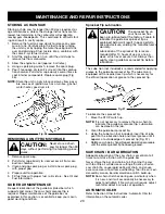
Page 15: ...e that the unit cannot start WARNING A good preventive maintenance program of regular inspection and care will increase life and improve performance of your chain saw This maintenance checklist is a guide for such a program Cleaning adjustment and part replacement may be required under certain conditions at more frequent intervals than those indicated CUSTOMER RESPONSIBILITY CHECK FOR LOOSE SCREWS...

Page 16: ...r 4 Guide the drive links into the groove H and around the end of the bar Fig 25 5 The chain will be tight so you will have to rotate the clutch clockwise by hand so the chain engages the bar sprocket 6 Replace the outer guide bar plate I so the bent edges top and bottom are directed away from the chain Fig 27 7 Install the Chain Brake cover Fig 27 Make sure the chain does not slip off of the bar ...

Page 17: ...on and tighten the bar retaining nuts securely A new saw chain stretches requiring adjustment after as few as 5 cuts This is normal with a new chain and the interval between future adjustments will lengthen quickly CAUTION If saw chain is TOO LOOSE or TOO TIGHT the sprocket bar chain and crank shaft bearings will wear more rapidly Study Fig 29 for information concerning correct cold tension A corr...

Page 18: ... wil be drawn into engine and damage it Keep the air filter clean CAUTION To avoid serious per sonal injury always turn your unit off and allow it to cool before you clean or service it WARNING Never operate saw without the fuel filter The fuel filter should be replaced after each 20 hours of use Drain fuel tank before changing CAUTION A B Fig 31 Fig 32 B A MAINTENANCE REQUIREMENTS CHECK FOR DAMAG...

Page 19: ... a new spark plug champion RDJ8J or equiv alent NOTE A resistor spark plug must be used for replace ment part no 9295 320001 NOTE This spark ignition system meets all requirements of the Canadian Interferen Causing Equipment Regulations Do not sand blast scrape or clean electrodes Grit in the engine could damage the cylinder WARNING Fig 35 CARBURETOR ADJUSTMENT The carburetor was pre set at the fa...

Page 20: ... sprocket tip The sprocket tip on your new saw has been pre lubricated at the factory Failure to lubricate the guide bar sprocket tip as explained below will result in poor perform ance and seizure voiding the manufacturer s warranty Lubrication of the sprocket tip is recom mended after 10 hours of use or once a week which ever occurs first Always thor oughly clean guide bar sprocket tip before lu...

Page 21: ...nt after as few as 5 cuts This is normal during the break in period and the interval between future adjustments will begin to lengthen quickly MAINTENANCE AND REPAIR INSTRUCTIONS Never have more than 3 links removed from a loop of chain This could cause dam age to the sprocket WARNING INERTIA CHAIN BRAKE ACTION NOTE THIS SAW IS EQUIPPED WITH AN INERTIA CHAIN BRAKE IF THE SAW KICKS BACK WHILE IN US...

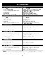
Page 22: ...lug 3 Clean gap or replace plug 4 Empty fuel tank 4 Fill fuel tank with properly mixed fuel 5 Primer bulb was not pressed enough 5 Press primer bulb fully and slowly 10 times UNIT WON T START OR STARTS BUT WILL NOT RUN UNIT STARTS BUT ENGINE HAS LOW POWER ENGINE HESITATES NO POWER UNDER LOAD C A U S E A C T I O N 1 Fuel filter is plugged 1 Replace the fuel filter 2 Incorrect lever position 2 Move ...

Page 23: ...00 rpm Operating RPM 7 200 rpm Ignition Type Electronic MAX FIRE IGNITION Ignition Switch Slide Switch Spark Plug Gap 0 025 in 0 635 mm Lubrication Fuel Oil Mixture Fuel Oil Ratio 40 1 Carburetor Diaphragm All Position Starter Incredi Pull Starting Auto Rewind Muffler Baffled with Guard Throttle Manual Spring Return Fuel Tank Capacity 16 8 oz 496 8 ml Throttle Control Finger Tip Trigger Approximat...

Page 24: ...310004 9SKKZY10 14 01 9124 310202 9070 310002 9129 310209 9013 310201 9252 310002 9131 310206 9043 310203 9043 310202 9SKKBY6 19 0 375 9SJKB 12 14 1 5 9228 31B202 9228 310216 9SKKBY10 14 02 9SKKBY10 14 0 68 9228 310204 9067 310202 9214 310101 9228 310230 9114 310202 9013 310202 9228 310213 9228 310214 9228 310232 9SKKBY8 16 0 625 9SKKBY 8 16 1 9010 310203 9228 310222 9WFB 4 9 17 9024 310206 9010 3...

Page 25: ...sibilities you should call 1 800 4 MY HOME Manufacturer s Warranty Coverage The warranty period begins on the date the engine or equipment is delivered to the retail purchaser The manufacturer warrants to the initial owner and each subsequent purchaser that the engine is free from defects in mate rial and workmanship which cause the failure of a warranted part for a period of one year Repair and r...

Page 26: ...26 ...

Page 27: ......

Reviews: