ASSEMBLY INSTRUCTIONS
ATTACH INTERMEDIATE TUBE AND CON-
CENTRATOR NOZZLE
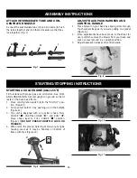
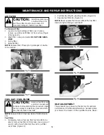
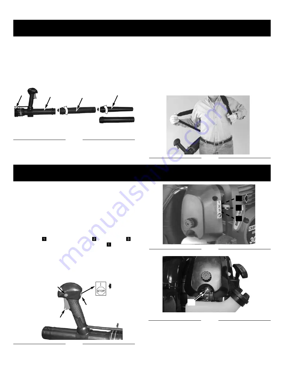
Connect the intermediate tube (H) and air nozzle (I). Push
the tubes together and turn them clockwise so that they
lock together. (Fig. 7)
ADJUST BACK PACK HARNESS AND
CONTROL HANDLE
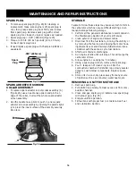
1.
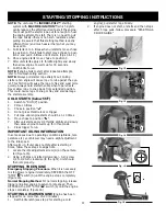
Place blower on your back by slipping arms through
the shoulder straps as if you were putting on a jacket
(Figure 8).
2.
Once adjustments have been made, to the straps for
user comfort, remove the blower from your back and
place on level ground in an upright position.
3.
Adjust backpack harness and control handle.
Fig. 7
B
D
H
I
45mm
56mm
Fig. 8
STARTING/STOPPING INSTRUCTIONS
Fig. 9
A
C
B
Fig. 11
D
10
STARTING A COLD ENGINE (Above 55
˚
F)
Fill fuel tank with proper gas and oil mixture. See FUEL
AND LUBRICATION. Set unit upright on ground so that it
rests on the back pack frame.
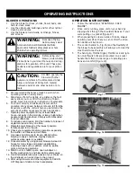
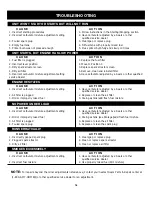
1. Move on/off ignition switch (A) to the “RUN (I) ” posi-
tion. (Figure 9)
2. Pump primer bulb10 X by pushing up on the bulb(D).
(Figure 11)
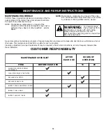
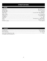
3. Your unit is designed with a 3 position choke: FULL
CHOKE “
”, PARTIAL CHOKE “
”, and RUN “
”.
Move choke lever to FULL CHOKE “
” position.
(Figure 10)(
DO NOT PRESS THROTTLE LOCK OR
TRIGGER.
)
4. With unit on the ground, hold top of blower-not engine
housing cover as it may be hot-step on bottom of
frame with foot. (Figure 12)
Fig. 10
1
2
3


