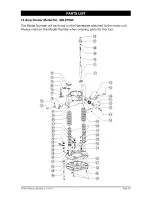
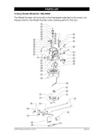
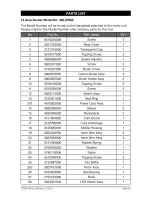
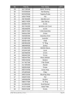
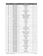
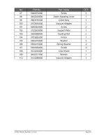
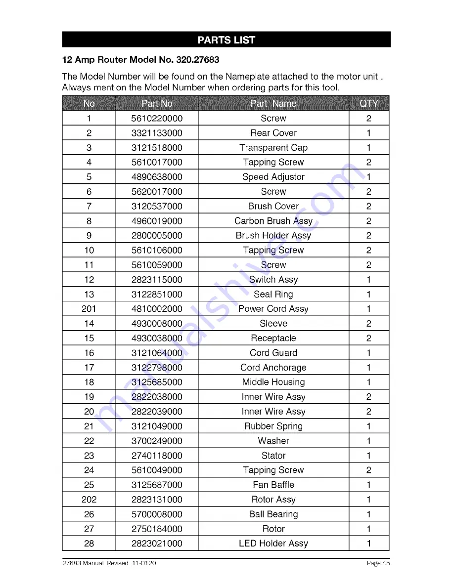
background image

Summary of Contents for 320.27683

Page 1: ...ase Model No 320 27683 WARNING To reduce the risk of injury the user must read and understand the Operator s manual before using this product WARRANTY SAFETY UNPACKING DESCRIPTION OPERATION MAINTENANCE TROUBLESHOOTING ESPANOL Sears Brands Management Corporation Hoffman Estates IL 60179 U S A www craftsman com ...

Page 2: ...w craftsman com This warranty is void if this product is ever used while providing commercial services or if rented to another person This warranty gives you specific legal rights and you may also have other rights which vary from state to state Sears Brands Management Corporation Hoffman Estates IL 60179 A WARNING Some dust created by using power tools contains chemicals known to the state of Cal...

Page 3: ...ion which if not avoided could result in minor or moderate injury It may also be used without the safety alert symbol as an alternative to NOTICE 2 Always follow the safety precautions to reduce the risk of fire electric shock and personal injury NOTICE NOTICE is the preferred signal word to address practices not related to personal injury The safety alert symnol not be used with this signal word ...

Page 4: ... use in damp locations To reduce the risk of injury user must Read The Operator s Manual read and understand operator s manual before using this product O Always wear safety goggles or safety Eye Protection glasses with side shields and a full face shield when operating this product Alert Precautions that involve Safety your safety No Hands Symbol Failure to keep your hands away from the blade wil...

Page 5: ...use you to lose control ELECTRICAL SAFETY Power tool plugs must match the outlet Never modify the plug in any way Do not use any adapter plugs with earthed grounded power tools Unmodified plugs and matching outlets will reduce risk of electric shock Avoid body contact with earthed or grounded surfaces such as pipes radiators ranges and refrigerators There is an increased risk of electric shock if ...

Page 6: ...l reduce personal injuries Prevent unintentional starting Ensure that the switch is in the OFF position before connecting to a power source and or battery picking up or carrying the tool Carrying power tools with your finger on the switch or energizing power tools that have the switch on invites accidents Remove any adjusting key or wrench before turning the power tool on A wrench or a key left at...

Page 7: ...h these instructions taking into account the working conditions and the work to be performed Use of the power tool for operations different from those intended could result in a hazardous situation A_ WARNING When using power tools basic safety precautions should always be followed to reduce the risk of fire electric shock and personal injury WARNING The operation of any tool can result in foreign...

Page 8: ...ments will not be accurate Do not hand hold the router in an upside down or horizontal position The motor can separate from the base if it is not properly attached according to the instructions Tighten the collets nut securely to prevent the cutter bit from slipping If the collet nut is not securely tightened the cutter bit may detach during use causing serious personal injury Never tighten a coll...

Page 9: ...s personal injury If using a router table large bits should be used for edging only Be sure that the cutter bit is centered in a template guide sold separately prior to template guide applications to avoid personal injury or damage to finished work Do not remove more than 1 8 inch in a single pass Excessive depth of cut can result in loss of control that could result in personal injury After compl...

Page 10: ...llet nut is already installed on the router 2 screws for attaching the vacuum ports to plunge base Collet nut wrench 2 Chip shields one each for the fixed and plunge bases Edge guide Depth adjustment wrench Carry case Manual 3 Inspect the items carefully to make sure that no breakage or damage has occurred during shipping If any of the items mentioned is missing refer to PARTS LIST illustration re...

Page 11: ... for Plunge Base 2 chip shields Vacuum Port for fixed Base _ _ 2 screws for attaching port to plunge base _ 1 4 in and 1 2 in Collet Nut Edge Guide Depth Adjustment Wrench Collet Nut Wrench 27683 ManuaLRevised_11 0120 Page 11 ...

Page 12: ... 120 volt 60 Hz AC only outlet check the power supply This router has an 8 ft 2 wire power cord no adapter needed Motor Housing Fig 1 Live Tool Indica tor Light Cap Replaceable Carbon Brushes Sold separately On Off Speed Quick Clamp Switch System Adjust ment Dial with Dept Fixed Base Indicator Ring Spindle Lock Micro Ad ust Knob Plunge Depth Locking Level Locking Knob Depth Rod Depth Stop Turret Q...

Page 13: ...he project you are attempting Before use of this product familiarize yourself with all operating features and safety rules The Router Combo has the following features 1 12 0 Amp 2 Peak HP Variable Speed Motor runs at 10 000 to 25 000 RPM no load speed 2 Variable Speed Dial for matching the speed to the material and cutter bit size 3 Electronic Feedback Circuitry provides soft starts for longer mot...

Page 14: ... cutter diameter larger than 1 1 4 inch with the included sub bases as it will not pass through the sub base opening 14 Motor Housing constructed of Precision Milled Cast Aluminum for strength and exact fit into bases 15 High impact Resistant Motor Housing Top Cap and Handles on bases help protect tool from damage 16 Heavy duty Edge Guide for most routing applications such as decorative edging gro...

Page 15: ... inches To use cutter bits with larger diameters use sub bases with larger openings sold separately at Sears stores or other Craftsman outlets _ WARNING Always turn the motor off and unplug the router before making any adjustments or installing accessories Failure to unplug the router could result in accidental starting which can cause serious personal injury INSTALLING AND REMOVING THE CUTTER BIT...

Page 16: ...revent damage to the tool do not tighten the collet nut without a cutter bit installed REMOVING THE CUTTER BIT FROM FIXED BASE 1 Turn the motor off and unplug the router from the power source NOTE See the instructions for removing the motor housing from the fixed base 2 Remove the motor from the fixed base 3 Set the motor upside down on its top cap with the collet nut pointing up 4 Press the spind...

Page 17: ...op cap with the collet nut pointing up 4 Press the spindle lock button to engage and lock the spindle shaft and the collet nut Fig 6 5 Place the wrench on the collet nut and turn it counterclockwise to slightly loosen collet nut 6 Remove the cutter bit shank Fig 6a NOTE The collet nut is self releasing it is not necessary to strike the collet nut to free the router cutting bit If the cutting bit s...

Page 18: ...ing any adjustments or installing accessories Failure to turn the motor off and unplug the router could result in accidental starting which can cause serious personal injury To Install Motor in Fixed Base Fig 4 1 Turn router motor off and unplug from power source 2 Place fixed base on flat surface 3 4 With back of fixed base facing you open the motor clamp A Press in Coarse Adjustment Knob B while...

Page 19: ...he router from the power source 2 3 Place the router plunge base and motor housing on a flat surface With the back of the plunge base facing you open the motor clamp A and make sure that the plunge action is in the UP position with the plunge lock lever B locked Lift the motor straight up out of the base sliding the motor housing slot C free from the pin in the plunge base Fig 5 c A_ 4 5 Set the m...

Page 20: ... counter clockwise to see if the bit lowers and raises If it does not press in the Coarse Adjustment Knob and turn the Fine Adjustment Dial until the gears engage then reset zero 0 on Depth Indicator Ring D The Depth Indicator Ring D located on the Fine Adjustment Dial is marked in 1 64 inch increments Turning the fine adjustment dial clockwise 180 1 2 turn lowers the cutter bit 1 16 inch One full...

Page 21: ...ause a rough cut and be difficult to guide and control For these reasons do not exceed 1 8 in depth of cut in a single pass Deep Cuts The proper cutting depth for each pass is always determined by the material the cutter bit size and type and the power of the motor Always make several progressively deeper cuts by starting at one depth and then making several passes each time increasing the cutting...

Page 22: ...th Stop Turret are used to control the plunge action cutting depth as follows 1 Turn the motor off and unplug the router from the power source 2 Place the router on a flat level surface 3 With the cutting bit already installed lower the plunge action until the cutter bit makes contact with the flat level surface on which the router is sitting Lock the plunge depth locking lever F This position is ...

Page 23: ...ogressively deeper cuts by starting with the highest step on the depth stop turret and after each cut rotate the turret to the next lower step until the Iowerst step is reached Each of the steps progresses by 1 4 inch increments The 4 steps represent a total of 0 inch to 3 4 inch with a full 360 rotation of the turret Repeat this process if necessary Micro adjustments with the Depth Stop Rod and D...

Page 24: ...ft side marked 1 or ON To turn the motor OFF push the toggle switch to the right side marked 0 or OFF Always hold the router and the cutter bit away from the workpiece when turning the toggle switch On Only contact the workpiece with the router and cutter bit after the router has reached the full selected speed Only remove the router and cutter bit from the workpiece after turning the router motor...

Page 25: ... simply insert the edge guide rods into the edge guide mounting slots either from the left or the right For fix base Tighten the lever on the left by turning it clockwise to secure the edge guide rod Fig 14 Tighten the lever on right by turning counterclockwise to secure the rod Fig 14 For plunge base Tighten the lever on the left by turning it counterclockwise to secure the edge guide rod Fig 14a...

Page 26: ...ng used WARNING Before operating your router follow all safety instructions in this manual Failure to do so could result in serious personal injury NOTE Choose the applicable cutting speed according the bit diameter and the material being cut Variable Speed Selection Chart Never exceed these bit speeds Cutting Bit Diameter Speed UP to 1in 25mm 6 1 1 4 in to 2in 30 50mm 4 5 2 1 4 in to 2 1 2 in 55 ...

Page 27: ...e base depends on the type of routing you are going to produce Edge Routing or Internal Routing as discussed on the following pages DEEP CUTS The proper cutting depth for each pass is always determined by the material the cutter bit size and type and power of the motor Always make several progressively deeper cuts start at one depth and then make several passes each time increasing the cutting dep...

Page 28: ... Always securely clamp your workpiece and keep a firm grip on the router base with both hands at all times Failure to do so could result in loss of control causing possible serious personal injury _1 WARNING Removing the cutter bit from the workpiece while it is still rotating could damage the workpiece and result in loss of control causing serious personal injury INTERNAL ROUTING WITH FIXED BASE ...

Page 29: ...otor build up to its full selected speed see Fig 20 2 To begin your cut unlock the plunge lock lever and gently lower the plunge action evenly into the workpiece 3 When the desired depth of cut is achieved lock the plunge lock lever Down and proceed to make your cut 4 When the cut is completed turn the motor OFF and let the cutter bit come to a complete stop Fig 20_i Edge Feed Direction Plunge 5 W...

Page 30: ...all mills are often used to make relief carvings Veining bits are used to carve small intricate details NOTE Making a single deep cut is never advisable Smaller diameter bits are easily broken by too much side thrust and torque Larger bits will cause a rough cut and be difficult to guide and control For these reasons do not exceed 1 8 in depth of cut in a single pass A_ WARNING Always securely cla...

Page 31: ...er of the pilot that is used determines the maximum cut width that can be made with the pilot against the workpiece edge the small pilot exposes the entire bit the large one reduces this amount by 1 16 in Any of the piloted cutter bits can be used without a pilot for edge shaping with guides _ WARNING Always securely clamp your workpiece and keep a firm grip on the router base with both hands at a...

Page 32: ...ternal cut such as a groove dado or slot always try to have the guide you are using with the router edge guide straight edge board guide on the right hand side of the router as you make the cut Fig 24 When the guide is positioned on the right hand side of the router the router travel should be from left to right and counterclockwise around curves see Fig 24 This counterclockwise action around the ...

Page 33: ...the bites become so large that chips become partially cut off causing splintering and gouging of the workpiece The router will make clean smooth cuts if allowed to run freely without the overload of forced feeding You can detect forced feeding by the sound of the motor Its usual high pitched whine will sound lower and stronger as it loses speed Holding the router against the workpiece will also be...

Page 34: ...the chip shield from the plunge base simply loosen the screw and take the chip shield off the base Fig 26a Fig 26a _1 WARNING The chip shield helps to keep dust and chips away from the operator they will not stop objects larger than woodchips that may be thrown from the bit _ WARNING Always have the appropriate chip shield in place on the base when operating the router A_ WARNING Always turn the r...

Page 35: ...H Figs 28 28a and 28b _ NOTE The Depth Adjustment wrench supplied is used to adjust the depth when the router is fixed to the router table Model No 320 28160 sold separately _ WARNING Always read and follow all directions for mounting the router to a router table and for use of the router table WARNING Always turn the router motor Fig 28 off and unplug the router from the power source before makin...

Page 36: ... collet nut down 4 When the desired depth of cut is set tighten the router motor clamp The precise depth of cut can be measured with a ruler Fig 28b Plunge Base Router When using the plunge base to attach the router to the router table the bit depth can be adjusted by turning the depth rod clockwise or counterclockwise with the wrench supplied Fig 28b 1 Turn off the router 2 Loosen the router moto...

Page 37: ...tant that the tool is cleaned frequently by blowing with an air jet A_ WARNING Always wear safety goggles or safety glasses with side shields during power tool operations or when blowing dust If operation is dusty also wear a dust mask ROUTINE MAINTENANCE _ WARNING Do not at any time allow brake fluids gasoline petroleum based products penetrating oils etc to come in contact with plastic parts Che...

Page 38: ...d the need for a break in period 4 Insert new brush assemblies into the guide channels with the carbon part going in first being certain to fit the two metal ears into their slots in the channel Fig 29 5 Remember to replace both end caps after inspecting or servicing brushes Tighten the caps snugly but do not over tighten The router should be allowed to run in run at no load without a cutter bit f...

Page 39: ... are not recommended for this tool might be dangerous and could result in serious injury Sears and other Craftsman outlets offer a large selection of Craftsman router accessories designed for specific routing applications There is a large selection of Craftsman Router Cutting bits available in High Speed Steel or Carbide Tipped High Speed Steel for all your routing needs In addition to a wide vari...

Page 40: ...n round nose 1 2 in 90 d v groove 1 2 x 1 in 3 8x1 2 in flush trim flush trim 1 2 in 1 4 in flush trim _ flush trim 3 8 in keyhole 1 2 in cove 1 4 in cove 3 8 in _ 1 4 in round over i l round over 1 8 in _ round over 1 2 in round over straight dovetail round nose v groove flush trim keyhole cove round over 27683 ManuaLRevised_11 0120 Page 40 ...

Page 41: ...bead 1 4 in roman ogee 3 8 in rabbeting 1 4 in veining 1 2 in core box 1 2 in mortising 1 4 in panel pilot 1 3 8 in 45 ochamfer bead cove classiccove bead Roman ogee rabbeting veining core box mortising panel pilot chamfer 27683 ManuaLRevised_11 0120 Page 41 ...

Page 42: ...mp Router Model No 320 27683 The Model Number will be found on the Nameplate attached to the motor unit Always mention the Model Number when ordering parts for this tool 27683 Manual_Revised_11 0120 Page 42 ...

Page 43: ...mp Router Model No 320 27683 The Model Number will be found on the Nameplate attached to the motor unit Always mention the Model Number when ordering parts for this tool 27683 ManuaLRevised_11 0120 Page 43 ...

Page 44: ...mp Router Model No 320 27683 The Model Number will be found on the Nameplate attached to the motor unit Always mention the Model Number when ordering parts for this tool 27683 ManuaLRevised_11 0120 Page 44 ...

Page 45: ... 2 10 5610106000 Tapping Screw 2 11 5610059000 Screw 2 12 2823115000 Switch Assy 1 13 3122851000 Seal Ring 1 201 4810002000 Power Cord Assy 1 14 4930008000 Sleeve 2 15 4930038000 Receptacle 2 16 3121064000 Cord Guard 1 17 3122798000 Cord Anchorage 1 18 3125685000 Middle Housing 1 19 2822038000 Inner Wire Assy 2 20 2822039000 Inner Wire Assy 2 21 3121049000 Rubber Spring 1 22 3700249000 Washer 1 23...

Page 46: ...or 1 42 3550841000 Shaft 1 43 5660005000 E Ring 4 44 3660498000 Spring 4 45 3126054000 Handle Sleeve 4 46 3705047000 Lever 4 47 5620466000 Screw 2 48 5620467000 Screw 2 49 5650407000 Wave Washer 4 50 5650166000 Washer 2 51 3121637000 Chip Shield 1 52 3121635000 Handle 4 53 5620024000 Screw 4 54 2823122000 Lever Assy 2 55 3703872000 Plate 1 56 2823126000 Mounting Assy 1 57 5630015000 Nut 2 58 56500...

Page 47: ...8000 Cap 1 77 5630016000 Nut 1 78 3123497000 Cover 1 79 2823123000 Plunge Frame 1 80 3660254000 Torsion Spring 1 81 5640045000 Bolt 1 82 3420398000 Plunge Lock Lever 1 83 5650007000 Spring Washer 1 84 5620040000 Screw 1 85 3123581000 Bollows Seal 2 86 3660166000 Spring 2 87 5620103000 Screw 2 88 3700078000 Wave Washer 1 89 3420387000 Turntable 1 90 5700046000 Steel Ball 1 91 3660030000 Spring 1 92...

Page 48: ...dapter 1 101 5620353000 Screw 2 102 3123500000 Support Plate 1 103 3550588000 Guiding Rod 2 104 3703925000 Fence 1 105 5650013000 Washer 2 106 5650015000 Spring Washer 2 107 5620050000 Screw 2 108 3123344000 Chip Shield 1 109 3402471000 Wrench 1 110 3123286000 Vaccum Adapter 1 27683 ManuaLRevised_11 0120 Page 48 ...

Page 49: ...27683 Manual_Revised_11 0120 Page 49 ...

Page 50: ...27683 Manual_Revised_11 0120 Page 50 ...

Page 51: ...27683 Manual_Revised_11 0120 Page 51 ...

Page 52: ... carry in items like vacuums lawn equipment and electronics call anytime for the location of the nearest Sears Parts Repair Service Center 1 800 488 1222 U S A 1 800 469 4663 Canada www sears com www sears ca To purchase a protection agreement on a product serviced by Sears 1 800 827 6655 U S A 1 800 361 6665 Canada Parapedir serviciode reparacidn Au Canada pour service enfrangais a domicilio y pa...

Reviews: