background image

Summary of Contents for 351.215680

Page 1: ...NDER WITH DUST COLLECTION Model No 351 21 5680 CAUTION Read and follow all Safety Rules and Operating Instructions before First Use of this Product Sears Roebuck and Co Hoffman Estates IL 60179 U S A www seam com craftsman 22118 02 Draft 05 17 04 ...

Page 2: ... available for tool Three prong plug should be plugged directly into properly grounded three prong receptacle Extension cords should have a grounding prong and the three wires of theextensioncord shouldbe of the correctgauge Keep visitorsat a safe distance from work area Keep childrenout of workplace Make workshop childproof Use padlocks master switches or remove switch keys to prevent any uninten...

Page 3: ...ndwheel and secure in positionwith hex nut Remove socket head bolt and washer from shaft locatedon the outboard side of the bed Place handwheel onto shaft making sure that the slot in the handwheel engages the pin on the shaft Secure handwheel in position with bolt and washer Before drum sander is assembled a suitable location should be chosen The drum sander and stand weighs approximately 200 Ibs...

Page 4: ...15 Frequency 60 HZ Phase Single RPM 3450 Prewired 120V WARNING All electrical connections mustbe performed by a qualifiedelectrician WARNING Do not connect sander to the power source until an assembly steps have been completed POWER SOURCE The motor is designed for operation on the voltageand fre quency specified Normal loads willbe handled safely on volt ages not more than 10 above or below speci...

Page 5: ...type plugs and 3 pole receptacles which accept the tool plug If the extensioncord is worn cut or damaged in any way replace it immediately Extension Cord Length Wire Size A W G Up to 25 tt 12 25 50 ft 10 NOTE Using extension cords over 50 ft long is not recommended ELECTRICAL CONNECTIONS WARNING All electrical connectionsmust be performed by a qualifiedelectrician WARNING Make sure tool is off and...

Page 6: ...es of material that are shorter than 6 in length or thinnerthat Ys Prevent the workpiece from contacting the sanding belt before starting the tool Sand with the grain of the wood Never perform layout assembly or set up work on the table when the tool is operating Turn the tool OFF disconnectthe tool from the power source and clean the table work area before leaving the tool Never leave the work ar...

Page 7: ...rsuse to allow for belt stretch Adjustmentsto belt trackingcan also affect belt tension Belt shouldride cantered on the drive and idler rollers The drum sander is shipped withthe tracking and tension properly adjusted However ifadjustment is necessary Tensioning NOTE When adjustingbelt tension tighten or loosen both bolts the same amount to avoid affecting belt tracking DO NOT over tensionthe belt...

Page 8: ...s fiat acrossthe totalsurfacearea on both sides To do a quick check draw pencil lines extending across the width of the board at several places aloog the length of the board Reverse the board end for end and run the board through the sander if the sanding table is set properly the drawn lines will disappear If the lines still appear on the left or right side of the board the table height must be a...

Page 9: ... the ele vating screws Adjust tension and tracking refer to Adjusting Tracking and Tension of Feed Belt in the manual Elevating Screws Figure 18 Changing Feed Belt RETURN ROLLER Refer to Figure 19 The drum sander has a return roller on the drum cover so that the workplace can be easily moved to the frontof the sander for another pass PassWorkplece Backto Operator TOOLBOX Refer to Figure 20 Tool st...

Page 10: ... damaged in any way have it replaced immediately Replace worn abrasive when needed Replace any damaged or missing parts Use parts list to order parts Any attempt to repair motor may create a hazard unless repair is done by a qualified service technician Repair service is available at your nearest Sears store REMOVING AND REPLACING DRIVE BELTS Loosen and remove the six socket head bolts shown and r...

Page 11: ...ce the feed ddve belt See Figure 24 Figure 24 To remove and replace the variable speed belt the outer variable speed drive pulley must be removed Loosen and remove the socket head bolt washer and pulley See Figure 25 Figure 25 Reassembte in reverse order 11 ...

Page 12: ...motor or loose connections 3 Low voltage 4 Incorrect fuses or circuit breakers in power line 1 inspect line cord or plug for damaged insulationand shorted wires 2 Inspect all lead connections on motor for loose or shorted terminals or worn insulation on wires 3 Install correct fuses or circuitbreakers 4 Push thermal overload button to reset 1 Reduce the Loadon the power line 2 Increase wire sizes ...

Page 13: ...Service Record Craftsman 18 x 36 Drum Sander with Dust Collection DATE MAINTENANCE PERFORMED REPLACEMENT PARTS REQUIRED I 13 ...

Page 14: ...Model 351 215680 Figure 26 Replacement Parts Illustration for Drive 2 11 14 I 18 i7 38 29 36 35 J J J 32 2O J 9 22 23 28 14 ...

Page 15: ...36 STD304460 V Belt 1 37 STD863510 5 0 8 x 10mm Pan Head Screw 1 Standard hardware item available locally A Not shown KEY NO PART NO DESCRIPTION QTY 38 18151 00 Knob 1 39 STD863512 5 0 8 x 12mm Pan Head Screw 3 40 STD870620 6 1 0 x 20mm Socket Head Bolt 2 41 22142 00 Cover 1 42 22143 00 Gear 1 43 04869 00 5 0 8 x 6mm Set Screw 1 44 22144 00 Gear with Scale 1 45 22145 00 10 1 5 x 12mm Socket Head B...

Page 16: ...Model 351 215680 Figure 27 Replacement Parts Illustration for Table 19 55 54 7 20 19 21 52 42 43 8 16 ...

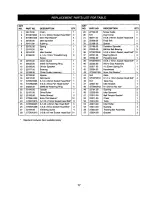
Page 17: ...8 x 8ram Socket Head Bolt 2 27 22194 00 Elevating Screw 4 28 STD870512 5 0 8 x12 mm Socket Head Bolt 21 Standard hardware item available locally KEY NO PART NO DESCRIPTION QTY 29 22195 00 Screw Guide 4 30 N A Dust Cover 1 31 08541 00 5 0 8 x 60mm Socket Head Bolt 4 32 22306 00 Feed Belt 1 33 22198 00 Spacer 4 34 22199 00 Elevation Sprocket 3 35 22200 00 6904zz Ball Bearing 3 36 STD870535 5 0 8 x 3...

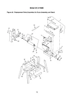
Page 18: ...Model 351 215680 Figure 28 Replacement Parts Illustration for Drum Assembly and Stand 28 I l 14 32 _7 18 36 34 18 ...

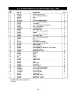
Page 19: ...Bolt Chip Deflector 6 1 0 x 1OmmSocket Pan Head Screw 5 0 6 x 18ram Set Screw 5 0 8ram Hex Nut Rear Pressure Plate 10 1 5 x 10rnmSocket Head Bolt Bushing 6 1 Ox 10ram Socket Head Bolt Front Pressure Plate 10 1 5 x 25ram Socket Head Bolt Clip Drum Housing Bearing Mount with Bearing 6 1 0 x 12mm Socket Head Bolt Bearing Housing Abrasive Belt 80 Grit Drum Assembly Incl Key Nos 6 14 26 27 28 6205zz Ba...

Page 20: ...ment and electronics call or go on line for the location of your nearest Sears Parts Repair Center 1 800 488 1222 Call anytime day or night U S A only www sears com To purchase a protection agreement U S A or maintenance agreement Canada on a product serviced by Sears 1 800 827 6655 U S A 1 800 361 6665 Canada Para pedir servicio de reparaci6n a domicilio y para ordenar piezas 1 888 SU HOGAR _ 1 8...

Reviews: