background image

Summary of Contents for 351.217430

Page 1: ... DUST COLLECTION Model No 351 217430 CAUTION Read and follow all Safety Rules and Operating Instructions before First Use of this Product Sears Roebuck and Co Hoffman Estates IL 60179 U S A www sears con_craftsman 18236 03 Draft 07 01 04 ...

Page 2: ...ools in dangerous environments Do not use power toots in damp or wet locations Do not expose power tools to rain Work area should be properly lighted Proper electrical receptacle should be available for tool Three prong plug should be plugged directly into properly grounded three prong receptacle Extension cords should have a grounding prong and the three wires of the extension cord should be of t...

Page 3: ...ed with carrier Check for complete ness immediately report missing parts to dealer The planer comes assembled as one unit Additional parts which need to be fastened to planer should be tocated and accounted for before assembling A Planer B Handle Assembly C 6ram Flat Washer D 6 1 0 x 20mm Socket Pan Head Bolt E 6 1 0 x 25mm Socket Head Bolt F Pointer G Magnet 2 H 4ram HexWrench I Dust Chute J Half...

Page 4: ...convenient sawdust disposal trash can and plastic trash bag not included Mount planer to work bench or table before installing Dust Collection Set To use dust collection set with a trash can Place spring inside filter bag arm Slide arm with spring over dust chute Place band of the bag over rim of trash can and secure bag by tightening strap To use dust collection set with a trash bag Place spring ...

Page 5: ...is not permitted in Canada Where a 3 prong to 2 prong grounding adapter is permitted the rigid green tab or terminal on the side of the adapter must be securety connected to a permanent electrical ground such as a properly grounded water pipe a properly grounded outlet box or a properly grounded wire system Many cover plate screws water pipes and outlet boxes are not properly grounded To ensure pr...

Page 6: ...re cautions are understood see pages 2 3 and 6 Whenever adjusting or replacing any parts on planer turn switch OFF and remove plug from power source Make sure all guards are properly attached and securely fastened Make sure all moving parts are free from interference Always wear eye protection or face shield Make sure blades are aligned and properly attached to cutterhead Do not plug in planer unl...

Page 7: ...le D with pointer allows easy adjustment of relier case height DEPTH OF CUT GAUGE Refer to Figure 11 A spring loaded depth of cut gauge E is attached to front of rollercase The pointer on depth of cut gauge accurately displays the depth of cut per pass when workpieca is positioned below the gauge Cranking the handle C moves the rollercase down and the pointer shows depth of cut up to 3 Recommended...

Page 8: ... planing performance the depth of cut should be less than 1 Board should be planed with shallow cuts until the work has a level side Once a level surface has been created flip the lumber and create parallel sides Plane alternate sides until the desired thickness is obtained When halfof totaldepth of cut istaken from each side the boardwillhave a uniformmoisturecon tent and additionaldryingwill not...

Page 9: ...ickness Planer has return rollers A on top so assistant can pass work back to operator Figure 16 Return Rollers NOTE Assistant must follow same precautions as operator Surface that the planer will produce will be smoother if shallower depth of cut is used Avoiding Snipe Snipe refers to a depression at either end of board caused by an uneven force on cutterhead when work is entering or leaving plan...

Page 10: ...ade Latcx_k S Figure 19 RemoveBlade Replace with new blade and carefully position it on the two pins using the two magnets Replace gib and align the holes on the gib with holes on the blade using the two magnets Secure gib to cutterhead usingsix bolts removed earlier Depress latch to release cutterhead Release latch when cutterhead can be turned by hand Turn cutterhead by hand until it is stopped ...

Page 11: ... Pull handle off Pull knob Fig 21 Key No 40 off Remove four pan head screws Fig 21 Key No 15 from cover Fig 21 Key No 10 Remove cover Remove right side cover Fig 21 Key No 39 Remove V belt Fig 22 Key No 28 by walkingthe belt from both pulleys alternately Gently pull the belt while turning the pulleys at the same time Repeat with V belt Fig 23 Key No 78 Replace with new belts Walk each belt onto th...

Page 12: ...umns dirty 3 Elevation screws worn 4 Friction between rollercase and covers 5 Rollercase not parallel with planer base 6 Rollercase lockengaged 1 Clean and lubricate sprocketsand chain 2 Clean and lubricateelevation screws columns 3 Replace elevation screws 4 Clean and lubricate 5 Adjust rollercase See Adjusting Table Level 6 Release rollercase lock Board feeds inside but stops 1 Outfeed rollers c...

Page 13: ...erload 2 Improper capacity of circuit breaker or fuses 3 Dull blades CORRECTIVE ACTION 1 Check collector bag connections Check collector hose connections 2 Dust trapped under bag clamp or collector bag not sealed on flange 1 Turn collector off and let debris settle in collector bag Remove blade guard and clear chamber 2 Remove blade cover and tighten bolt Fig 22 Key No 19 1 Reduce depth of cut 2 C...

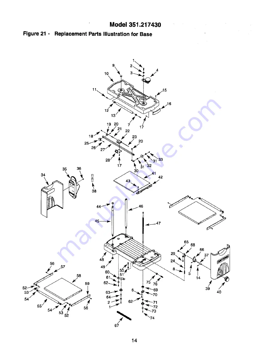
Page 14: ...Model 351 217430 Figure 21 Replacement Parts Illustration for Base 35 36 9 19 20 7 1_ 26 27 4 28 _ 38 j _1 22 54 56 58 65 68 66 14 ...

Page 15: ... Standard hardware item available locally A Not Shown KEY NO PART NO 38 16115 00 39 18591 00 40 18560 00 41 18616 00 42 18547 00 43 03855 00 44 00256 00 45 18526 00 46 18527 00 47 18534 00 48 18507 00 49 STD841217 50 STD833020 51 STD840610 52 18601 00 53 08662 00 54 09658 00 55 18615 00 56 00781 00 57 18563 00 58 18535 00 59 18590 00 60 18299 00 61 STD851005 62 05331 00 63 18339 00 64 18333 00 65 ...

Page 16: ...Model 351 217430 Figure 22 Replacement Parts Illustration for Rollercase 51 35 36 40 33 11 12 13 14 15 47 48 21 25 23 f 2 32 12 11 69 73 2 _ P 43 34 d 41 f 16 ...

Page 17: ... 2 1 2 2 1 1 1 1 1 1 1 2 1 1 1 1 1 4 4 4 1 1 2 1 1 KEY NO 37 38 39 4O 41 42 43 44 45 46 47 48 49 5O 51 52 53 54 55 56 57 58 59 60 61 62 63 64 65 66 67 68 69 7O 71 72 73 74 75 PART NO 18562 00 STD851005 08551 00 00814 00 18612 00 02702 00 18593 00 18513 00 18595 00 18589 00 05383 00 STD540501 00361 00 01474 00 18582 00 01548 00 STD851004 18579 00 18520 00 00781 00 18584 00 18574 00 18594 00 18494 0...

Page 18: ...Model 351 217430 Figure 23 Replacement Parts Illustration for Cutterhead and Gearing 48 55 51 65 63 64 67 68 69 71 7 3 76 77 78 79 2 _ 3 7 46 82 83 84 35 36 37 _X 87 86 85 4O 44 45 59 J 26 47 18 ...

Page 19: ...Bolt Outside Gear Plate Standard hardware item available locally A Not Shown QTY 1 1 1 4 1 1 1 1 3 2 1 2 1 2 1 1 1 1 1 1 2 2 1 2 1 2 1 4 4 4 4 1 2 1 1 1 1 1 1 1 1 1 2 4 1 KEY NO 46 47 48 49 5O 51 52 53 54 55 56 57 58 59 60 61 62 63 64 65 66 67 68 69 7O 71 72 73 74 75 76 77 78 79 8O 81 82 83 84 85 86 87 A PART NO DESCRIPTION 20038 00 18596 00 18267 00 18351 00 18329 00 20020 00 18577 00 STD315225 1...

Page 20: ... m_ scaracontra el polvo sial utilizar la herramienta se produce mucho polvo Estd alerta y piense claremente Nunca opere herramien tas mec_ nicascuando est_ cansado intoxicado o bajo la influenciade medicaci6n que produzca somnolencia PREPARE EL AREA DETRABAJO PARA LA TAREA A REALIZAR Mantenga el drea de trabajo limpia Las dreas de trabajo desordenadas atraen accidentes No use herremientas mec_ ni...

Page 21: ...transmisibn el portacuchilla y la euehilla en su lugar yen adecuadas condiciones de funcionamiento Introduzca la pieza de trabajo en la cuchilla o cortadora en sentido contrario al de rotaci6n PRECAUCION iPiense en a seguridad La seguridad es una combinaei6n del sentido com_n del operador y un estado de alerta permanente al usar la herramienta ADVERTENClA No trate de operar la herramienta hasta qu...

Page 22: ... de cerpinterfa que tengan un orificio do escape de polvo do 2V2 de didmetro La bolsa de filtrar se une a un cubo de basura de 30 galones o una boise pidstica para basura do 30 galones x 1 3 milipuigadas para permitir el desecho sencillo y prdcticode aserdn no se incluye el cubo de basura nila bolsa pldstica para basura Monte la copilladora en un banco de trabajo o mesa antes de instalar el Equipo...

Page 23: ...eldctrico o el enchufe no conecte el cable verde o verde y amarillo a un terminal cargado Un zbcalo para dos clavijasdeber_ ser reemprazado con un zdcalo para tree elavijasdebidamente conectado a tierra e instalado de acuerdo con las Normas para Instalaciones Eldctricas National ElectricCode y los c6digos y regulaciones locales ADVERTENClA 51o un electricista califlcadodebe cam biar los recept_cul...

Page 24: ...er minuto 16 000 Orificio rocolector de polvo 2V2 Dimensiones generales 21 A x 26V2 A x 35 2 P Motor 2V2HP desarrollo mdx 15 A 120 V Peso 97 Ibs REGLAS DE SEGURIDAD DE OPERACION ADVERTENCIA Para su propia seguridad lea todas las instruceionesy las precauciones antes de operar la herramienta ADVERTENCIA El funcionamiento de todas las herramientas mec_nicas puede hacer que sean lanzados a los ojos c...

Page 25: ...extrae a Ilave con el interrupter en la posiciSn ON encendido se puede Ilevar a la posici6n de apagado Flgura 11 Suba Bajela CaJade Rodlllos pero no a la de encendido A B Figura 10 Traba del Interruptor y Reajuste del Clrculto Para volver a insertar la llave deslfcela al interior de la ranura del interruptorbasra que se acople CORTACIRCUITO Consulte la Figura 10 La cepiliadora estd equipada con un...

Page 26: ...ue se crea una superficie nivelada paralela al lado opueste de la tabla El espesor que producirdla cepilladera se indicaen la escala D y el calibradorde profundidaddel corte E Ajuste previamente la cepilladoraal espeser deseado de acabade de la pieza de trabajo vali_ndese de la peri la F Consulte Calibradorprea justade del espesor de la pieza de trabajo en la pdgina 26 D Figura14 Profundldaddel Co...

Page 27: ...a Iongitudmayorde 24 deben tener mayor apoyo mediantepedestales de material independientes Coloque la pieza de trabajo con la care que se va a cepillar en la parte superior Encienda la cepilladore Haga descansar el extremo de la tabla en la placa del rodillode alimentaci6n y dirrjala hacia al interior de la cepilladora Suavemente deslice la pieza de trebajo hacia el interior del lado de alimentaci...

Page 28: ... Los imanes se pueden separar fdcilmente de Is cuba inclin 4ndoloshacia la izquierda o derecha PRECAUClON Los hordes de la cuchilla estdn extremada mente afilados Mantenga los dedos alejados de la cuchillas en todo momento La cuchilla ss mantiene an su ugarmediante dos pasadores Separe suavemente las cuchillasusadas de los pasadores mediante los dos imanes No toque la cuchilla con los dedos Use s6...

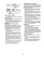
Page 29: ...e las poleas Se deben reemplazar las correas que est_n flojas Para reemplazar la correa en V Extraiga el tornillode cabeza hueca y la arandela plana Fig 21 Claves No 1 y 2 Retire la manivela Retire la perilla Fig 21 Clave No 40 Extraiga los cuatro tornillos de cabeza de placa Fig 21 Clave No 15 de la cubierta Fig 21 Clave No 10 Retire la cubierta Retire la cubierta del lado derecho Fig 21 Clave No...

Page 30: ...mente 1 Ruedas dentadas desgastadas 2 Cadena desgastada MEDIDAS CORRECTIVAS 1 Reemplace las cuchillas seg nlas instrucciones Consulte Mantenimiento 2 Soporte las tablas argas Consulte C6mo evitar el redondeo 3 Suavemente empuje la tabla cuando est_ en contacto con s61oun rodilloalimentador Consulte C6mo evitar el redondeo 4 Ajuste la caja de rodillos Consulte C6mo ajustar el nivel de la caja de ro...

Page 31: ...ricista califlcadodebe revisar el interruptory el cableado Reemplace la correa consulte C6mo reemplazar la correa en V Reajuste el calibrador de espesor consulte Calibrador de espesor de la pieza de trabajo 1 Veriflque las conexiones de la bolsa del recolector Verifique las conexiones de la manguera del recolector 2 Hay polvoatrapado debajo de la abrazadera de la bolsa o la bolsa del recolector no...

Page 32: ...s lawn equipment and electronics call or go on line for the location of your nearest Sears Parts Repair Center 1 800 488 1222 m _ m 2 i Call anytime day or night U S A only www sears com To purchase a protection agreement on a product serviced by Sears 1 800 827 m 6655 U S A 1 800 361 6665 Canada Pare pedir servicio de reparacidn Au Canada pour service en fran_ais a domicilio y para ordenar piezas...

Reviews: