background image

Summary of Contents for 351.217450

Page 1: ... DUST COLLECTION Model No 351 217450 Updated CAUTION Read and follow all Safety Rules and Operating Instructions before First Use of this Product Sears Roebuck and Co Hoffman Estates IL 60179 U S A wv _N sears co nllcnsftsman 20382 03 Draft 12 23 2003 ...

Page 2: ... power tools in damp or wet locations Do not expose power tools to rain Work area should be proper y lighted Proper electrical receptacle shouldbe available for tool Three prong plug should be pluggeddirectly into properly grounded thrae prong receptacle Extension cords should have a groundingprong and the three wires of the extensioncord should be of the correct gauge Keep visitors at a safe dist...

Page 3: ...ollection Set Auxiliary Table Hardware Bag Part No 21012 00 includes 10 32 x 23 d Socket Head Bolt 2 10 FlatWasher 2 Clamp 2 1 20x 11 Wing Screw 4 1 4 Flat Washer 4 Table Insert 4 Figure 1 UnpackingPlaner Molder The stand comes unassemb_edand packed along with the planer molder in the same box Locate and identify all parts before attemptingassembly A Frame long 2 B Frame short 2 C Brace long 2 D B...

Page 4: ... with socket head bolt usingwrench provided Insert plug into handle to oover bolt 4 Figure 6 Installing Dust Chute MOUNT PLANERJMOLDER TO STAND Refer to Figure 7 page 5 Planer molderis designed to be portable so it can be movedto job site but should be mountedto its includedstand for stability Make sure stand is located on a firm level surface in a place with ample lightingand correct power supply...

Page 5: ...ents Slide plastic trash bag inside and over bag support Let bag overlap 3 4 Place band of the filter bag over and into the channel of the bag support Secure in positionby tighteningstrapl INSTALL RETURN ROLLERS Refer to Figure 36 Insert return rollers Key No 11 into miler bushings Key Nos 1 and 2 5 POWER SOURCE WARNING Do not connect planer molderto the power source untilall assemblysteps have be...

Page 6: ...intainadequate voltage The minimumextension cord wire size is A W G 12 Do not use extension cords over 25 feet long Use only 3 wire extensioncords having3 prong grounding type plugs and 3 pole receptacles which accept the tool plug If the extensioncord is worn cut or damaged in any way replace it immediately Planer is supplied with a 3 HP motor installed The 120 Volt AC universalmotor has the foll...

Page 7: ...l overheat motor Allow automatic feed to function properly Use quality lumber Blades last longer and cuts are smoother with good qualitywood Do not plane material shorter than 17 narrower than wider than 15 or thinner than t 8 Never make planing cut deeper than _ Maintain the proper relationshipsof infeed and out feed table surfaces and cutterhead blade path Do not back the work toward the infeedt...

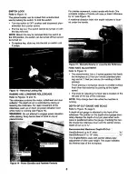
Page 8: ...engage power elevation while planing Keep hands clear of knob on top of planer molder Figure 14 Power Elevation and Feedrate Controls Figure 15 Manually Raising or Lowering the Rollercase FEED RATE ADJUSTMENT Refer to Figure 14 The planer molder has a 2 speed gearbox that feeds the workpiece at 22 feet per minute standard plan ing and at 11 feet per minute for moldingor finish planing Finish plani...

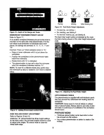
Page 9: ...ding Cut Figure 18 Feed Roller Height Adjustment For planing use setting I For molding use Setting II For the first molding cut use Setting III The feed roller height setting is indicated by the mark ing that is facing upward on the roller height adjustment shaft FEED ROLLER HEIGHT ADJUSTMENT Refer to Figures 18 and 19 Craftsman 15 planedmolder has three height settings for the feed rollers The pr...

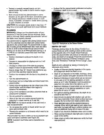
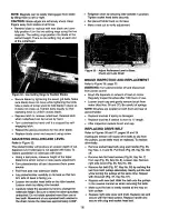
Page 10: ...ine with front or rear of planer molder Do not grasp any portionof board which has not gone past out feed roller Repeat this operation on all boards which need to be same thickness Planer molder has return milers on top so assistantcan pass work back to operator see Figure 20 NOTE Assistant must follow same precautionsas operator Surface that the planer molder produces is smoother if shallowerdept...

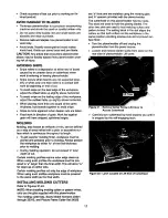
Page 11: ...outits length Toget superior moldingfinish workpieca must be planed and presized pdor to molding Always presize the workpieca to within _ of the final thickness prior to molding During moldingoperation do not exceed I total depth of cut Certain molding profiles require outer edge clean up When using such profiles the workpieca must be pre sized to t_ larger than the final width This will allow 1 f...

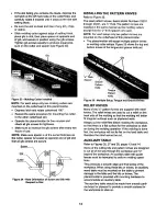
Page 12: ...sare used NOTE For each setup only two pattern knivesare mounted on the cutterheadof this planer mo der The planer molderwillacoept multiple pattern knives or moldingcuttersetups Figure 25 showsthe topand bottomknivesof the tongueand grooveknifeset Gib 1 4 Thick Spacer Groove Pattern Knife Tongue Pattern Knife Figure 25 Multiple Setup Tongue and Groove Knives RELIEF KNIVES Many of the pattern kniv...

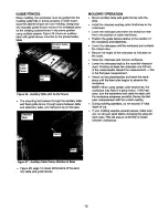
Page 13: ...guide fences relative to the positionof the workpiece and bits knives Lower the rollercase untilthe workpiecejust contacts the infeed roller Record the height of the rollercase as indicatedon the scale Raise the rellercase and removeworkpiece Lower the rollercase back to the recorded measure ment Continueto lower the rollercaseone full turn of the crank handle Recordthe measurement this is the fir...

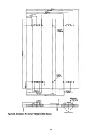
Page 14: ...m 43ram 6 Smm 169 5mm 38tmm 340 5mm 305 5mm 270 5mm I 4 1 273mm Mounting I Mounting Hole _r Clamp Set J 42 m_ 14 Smrn I i L l im 3 Wing Screw Flat Washer Figure 28 Dimensions for Auxiliary Table and Guide Fences 14 ...

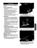
Page 15: ...s have plenty of grease Motor and cutterheed bearings are sealed and need no lubrication CHECK FORWORN BLADES Condition of blades affects precisionof cut Observe quality of cut which planer molder produces to check cendition of blades Dull blades tear rather than sever wood fibers and produce fuzzy appearance Raised grain occurs when dull blades pound on wood that has varying density Raised edge w...

Page 16: ... socket head bolts on the idler bracket Loosen chain by sliding idler bracket Carefully rotate the sprocketby hand to change the rolleroase height Be sureto leave the other sprockets untouched Do not rotate sprocketmore than one or two teeth Movement of one sprockettoothrelative to the chain moves the rollercaseapproximately0 006 Figure 33 Adjust Rollercase Level to Base Check and Lube Chain BRUSH...

Page 17: ...2 Elevation screws columns dirty 3 Elevationscrews worn 4 Frictionbetween ronercaseand covers i Rollercase not paroUelwith planer molder base 1 Clean and lubricate sprocket s and chain 2 Clean and lubricate elevationScrews columns 3 Replace elevationscrews 4 Clean and lubricate 5 Adjust rollercase See Adjusting Table Level Board feeds inside but stops 1 Ouffeed rollers cannot rotate due 1 Clear th...

Page 18: ...ise 1 Large debris or piece of wood in 1 Turn collectoroff and let debris settle in fan housing collector bag Remove blade guard and clear chamber 2 Loose fan 2 Open blade cover and tightenfan bolt Motor overheats 1 Motor ovedoad 1 Reduce depth of cut 2 Improper motor cooling 2 Clean sawdustfrom motor Trippingcircuitbreaker or 1 Motor ovedoad i1 Reduce depth of cut fuses 2 Improper capacityof circ...

Page 19: ...388 00 7 STD533107 8 08428 00 9 STD835080 10 STD851008 11 STD840812 A 20896 00 S_nda_ ha_wam i_m availa_elocatly A N_ Shown DESCRIPTION Leg Leg A Long Brace Short Brace Short Frame Long Frame _e 18 x Can iage Bolt 5 _ 18Washer Hex Nut 8 1 25 x 80ram Hex Head Bolt 8mm Flat Washer 8 1 25mm Hex Nut Stand Hardware Bag QTY i 2 2 2 2 2 24 24 4 8 4 1 19 ...

Page 20: ...0 Model 351 217450 Figure 35 Replacement Parts Illustration for Base j12 40 23 20 25 13 13 20 21 22 23 ...

Page 21: ...at Washer Standard hardware item availablelocally QTY 2 2 1 1 3 1 4 1 2 36 4 37 2 38 1 39 5 40 2 41 3 42 1 43 1 44 8 45 2 46 4 47 4 48 4 49 2 50 1 51 14 52 1 53 4 KEY NO 28 29 3O 31 32 33 34 35 PART NO STD841015 05374 00 20410 00 20411 00 20412 00 20413 00 STD840610 STD833020 00389 00 01465 00 20414 00 20415 00 20416 00 20417 00 20418 00 20419 00 16115 00 00814 00 07339 00 20421 00 20422 00 20423 ...

Page 22: ...Model 351 217450 Figure 36 Replacement Parts Illustration for Gearbox and Elevation Assemblies 36 35__ 37 _ 12 14 16 7_ 27 24 27 23 25 26 28 20 4 3O 7 6 22 ...

Page 23: ... Head Screw Fan Cover Dust Chute with Screw Fan Fan Assembly 5 0 8 x 10mm Socket Head Bolt Cover Retainer Handle Assembly Bushing Bracket 6 1 0 x 16ram Socket Head Bolt 3AMI 20 Retaining Ring 6 1 0 x 30ram Socket Head Bolt Transmission Assembly Clutch Assembly 4 x4 x 19mm Key 6 1 0 x 60mm Socket Head Bolt Idler Sprocket Assembly Plate 3AM1 15 Retaining Ring Chain Sprocket 6 1 0 x 65mm Socket Head ...

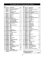
Page 24: ...Model 351 217450 Figure 37 Replacement Parts Illustration for Rollercase Assembly 33 3O 77 78 34 8O 81 65 62 16 26 24 ...

Page 25: ...11 1 1 1 1 1 2 2 2 1 2 5 1 3 2 1 1 1 2 2 1 2 1 1 1 1 1 1 1 5 1 1 1 1 1 2 4 40 40 4 2 KEY NO PART NO DESCRIPTION QTY 46 20476 00 Cable Bracket 1 47 00389 00 5 0 8 x 12mm Pan Head Screw 1 48 20477 00 Cable Pulley 1 49 05331 00 6 0 8 x 12mm Socket Head Bolt 12 50 STD851006 8mm Flat Washer 1 51 00483 00 8 1 25 x 25mm Socket Head Bolt 1 52 20478 00 Setting Ring 2 53 20483 00 Gib 2 54 20484 00 LockingBo...

Page 26: ...mRscara para la cars o una mRscara contra el polvo si al uti izarla herramienta se produce mucho polvo EetRalerta y piense claramente Nunca opere herramientas mec_nicas cuando estd cansedo intoxicadoo bajo la in fluencia de medicacibnque produzca somnolepcia PREPARE EL AREA DE TRABAJO PARA LA TAREA A REALIZAR Mantenga el Rrsa de trabajo limpia Las Rreas de trabajo desordenadas atraen accidentes No...

Page 27: ...acibn PRECAUClON iPiense en la seguddad La seguddad es una combinaci6n del sentido cemt3n del operador y un estado de alerta permanente al usar a herramienta ADVERTENClA No trate de operar la herramienta hasta que haya sido completamente armada seg n las instruc _ones Consulte las Figuras 1 y 2 Vedfique que no hayan ocurrido daSos durante el env o Si hay daSos se deber_ presentar un reclamo a la c...

Page 28: ...para que ta plataforma quede rectangular y nivelada v6ase ta Figura 4 Por ahora apriete las tuercas y los pernos manualmente Figure 3 Montar Pates en el Bastidor Sujete los riostras larga y corta alas patas Cotoque ta plataforma de soporta en posici6n vertical sobre el sueto y apriete bien todos los pemos y las tuarcas Figure4 PlataformaArmada INSTALACION DE LA MANIVELA Consulte la Figure 5 La man...

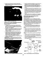
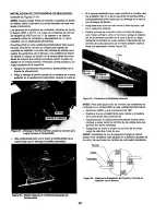
Page 29: ...o orificios de montaje de Is pieza fundida de la base Apdete los per nos con una arandela plans de 8 mm y una tuerca hexago nal per debajo de la parle superiorde la plataforma de soporte Apdete los cuatro pernos y aseg0rese que la cepilladora molduradoraquede montada firmemente en la plataforma INSTALAClON DEL EQUIPO RECOLECTOR DE POLVO DE MEDIA BOLSA Consulte la Figura 8 El Equipo Recolector de P...

Page 30: ...icadoque Instale un tomacorrlente adecuado Revise ped6dicamente los cordones de la herramienta y si est_n dafiados 116velos a un centre de servicioautodzado para que los reparen El conductorverde o verde y amarillo del cordbnes el cable de conexi6n a tierra Si es necesario reparar o reem plazar el cordbn el6ctricoo el enchufe no conecte el cable verde o verde y amarillo a un terminal cargado Un z6...

Page 31: ...x 11 Tamafio de ta base 32 x16 Ancho de la pieza de trabajo m_tx 15 Grosor de la pieza de trabajo mdx _ 6 Profundidad de corte mdxima _1 Cortes pot minuto 11 000 Velocidad de alimentacibn _ 11 22 FPM Dimensiones generales 56 Ax 34 A x 40 P Peso 150 Ibs NORMAS DE SEGURIDAD DE OPERAClON ADVERTENClA Parr su propia seguddad lea todas las instruccionesy las precauciones antes de operrr la herramienta A...

Page 32: ...a caja de rodillos presione hacia arfiba o abajo la palanca de elevaci6n mecdnica con el motor en marsha v_ asela Figura 14 ADVERTENClA No trate de accionar la eIevaci6n mecbni ca mientras cepilla Mantenga las manos alejadas de la pe ril a en la parte superiorde la capilladora molduradora Pedlla de ajuste de la de alimentaci6n Flgura t2 Intermptor de EncendldolApagado Cortaclmuito a Is Derecha TRA...

Page 33: ...a escala indica el tamai io finalizado de la pieza de trabajo Figure 16 F_scalay Cldlbrador de Profundldad dsl Corte CALIBRADOR PREAJUSTADO DEL ESPESOR DE LA PIEZA DE TRABAJO Consulte la Figura 17 En el lado derecho de la cepilladora molduradoraest_ instala da una perilla preajustada que regula el espesor de la pieza de trabajo Esta funci6n permits la rdpida producci6n de piezas de trabajo de igua...

Page 34: ...ontadas en el portacuchiltay con los rodillosde a imentaci6n de entrada y salida ajustadosa la altura corrects La cepil a doraJmoldurapora puede funcionara dos velocidadesde ali mentacibndiferentes La veloddad de alimentacibnse refiere a la velocidada la que avanza la madera a trav6s de la ce pil adoraJmolduradora El cepilladose puede realizara 22 PPM cepillado es_ndar o a 11 PPM pars Iograr el ac...

Page 35: ...esor es una m quina de precisibn para trabajar en madera y sblo se debe usar en madera de buena celidad No cepille tablas sucias la suc_edady piedrrs pequeSas son abrasivas y desgastan la cuchilla Extraiga los clavosy las grrpas Use la cepilladoraJmoldu radora para cortar madera solamente Evite los nudos La madera con uns veta atravesada tupida endurece los nudos Los nudos pueden soltarse y atasca...

Page 36: ... el bloque de fljaci6n AsegL_rese que la ranura est6 limpia y librede polvo asti lies o restos de material Deslice la fresa de moldurar centra el borde del bloque pars trlscar ponga la cuba en la tenure ponga el espacia dot en el extremo centrario de la cuss y fije en su lugar mediante los tornillosde cuba Apriete uniformemente los tomi osde cuss pars producirla misma presi6n sobre la fresa y el e...

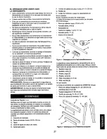
Page 37: ... un relieve en la parte posterior del moldeado de manera que el moldeado se adapte mejor a superficiesirregulares tales como paredes enlueidas Siempre corte el relieve pdmero antes de moldear la pieza de trabajo de manera que se produzca una superficie plana por la coal se pueda deslizar la pieza de trabajo durante la operaci6n de moldeado Si se realiza pdmero el moldeado la pieza de trabajo no de...

Page 38: ...4 5 m 5ram 381 mm 340 5 mm 305 5 mm 270 5 mm I I 3 J 273 mm Oril_do de montaje para Juego de rnordaza Odfldo de oa_ lU_ _e moro_J_ 3 3 Flgura 28 Dimenslones para la Mesa Auxlliar y Rebordes Gu a Tuerca de oreJetas Arandela p ana 38 ...

Page 39: ...suba o se baje Mantenga los retenes anticontragolpeslimpiosy funcionan do apropiadamente para ev_tarlesionesdebido al golpe Luego de cada diez horas de funcionamiento limpie el mecanismo de impulsibnde cadena engranaje Use un pario limpio y seco pars limpiar las astillasde readers polvo suciedad y grass vieja de las cadenas y engranajes LUBRICACION La superficie de la mesa se puede recubrircon un ...

Page 40: ...ensibn Afloje la cadena deslizando a abrazadera de tensibn Con mucho cuidado gire la rueda dentada con la mano pars cambiar la altura de la caja de rodillos Asegerese de no tocar las otras ruedas dentadas No gire la rueda denta da mds de uno o dos dientes El movimientode un diente de la rueda dentada en relaciSncon la cadena mueve la caja de rodillosaproximadamente 0 006 Vuelva a apretar la cadena...

Page 41: ... No 50 Extraiga dos tornillos de cabeza de plana Fig 35 Clave No 7 de ta cubierta Fig 35 Clave No 8 Afloje la ubierta Retire la cubierta de lado derecho Fig 35 Clave No 49 Retire la cornea dee ventJlador Fig 37 Clave No 28 haci_ndola pasar por las po eas altemadamente Tire suavemente de la correa mientras gira las poEeas al mismo tiempo Repita con la correa transmisora Fig 37 Clave No 67 Coloque l...

Page 42: ...llos La elevaci6n de la caja de rodillos 1 Ruedas dentadas o cadena sucias 1 Limpie y lubrique las ruedas dentadas y seajusta con diflcultad la cadena 2 Tornillosde eievaci6n columnas sucios 3 Tomillos de elevacibn desgastados 4 Fricci6n entre la caja de rodillosy las cubiertas 5 Caja de rodillosno se encuentra paralela respecto a la base de la cepilladora molduradora 1 Los rodillosde safida no pu...

Page 43: ...uada del cortacimuitoo los fusibles 3 Cuchil as desafiladas MEDIDA CORRECTIVA Reemplace la correa consulte C6rno reemplazar ia correa en V Reajuste el caflbradorde espesor consulte Calibrador de espesor de la pieza de trabajo 1 Verifique las conexionesde la bolsadel recolector Verifique las conexiones de la manguera del recolector 2 Hay polvoatrapado debajo de ia abrazadera de la bolsa o la bolsa ...

Page 44: ...wn equipment and electronics call or go on line for the location of your nearest Sears Parts Repair Center 1 800 488 1222 Call anytime day or night U S A only www sears com To purchase a protection agreement U S A or maintenance agreement Canada on a product serviced by Sears 1 800 827 6655 U S A 1 800 361 6665 Canada Para pedir servicio de reparaci6n a domicilio y para ordenar piezas 1 888 SU HOG...

Reviews: