13
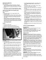
INSTALL MITER GAUGE
Refer to Figure 37.
• The miter gauge comes preassembled. Unpack the miter
gauge and clean thoroughly. Insert into storage slots on
right side of cabinet.
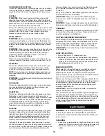
INSTALL PUSH STICK
Refer to Figure 38.
• Insert the push stick into brackets on left side of base.
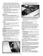
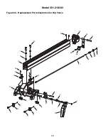
INSTALL RIP FENCE
Refer to Figure 39.
• Position rip fence assembly at end of saw. Be certain lock-
ing lever is in UP unlocked position.
• Place rip fence assembly onto rails, positioning clamp over
rear rail and then placing rip fence onto front guide rail.
• Rip fence should now ride freely on rip fence rails. Once
rip fence is completely installed, it should be parallel with
the miter gauge and perpendicular to the table. If not, refer
to “Rip Fence Adjustment” in the Operation section of this
manual.
INSTALLATION
GROUNDING INSTRUCTIONS
WARNING:
Improper connection of equipment grounding con-
ductor can result in the risk of electrical shock. Equipment should
be grounded while in use to protect operator from electrical shock.
• Check with a qualified electrician if grounding instructions
are not understood or if in doubt as to whether the tool is
properly grounded.
• This tool is equipped with an approved 3-conductor cord
rated at 300V and a 3-prong grounding type plug (see Figure
40) for your protection against shock hazards.
• Grounding plug should be plugged directly into a properly
installed and grounded 3- prong grounding-type receptacle,
as shown (Figure 40).
• Do not remove or alter grounding prong in any manner. In
the event of a malfunction or breakdown, grounding pro-
vides a path of least resistance for electrical shock.
WARNING:
Do not permit fingers to touch the terminals of
plug when installing or removing from outlet.
• Plug must be plugged into matching outlet that is properly
installed and grounded in accordance with all local codes and
ordinances. Do not modify plug provided. If it will not fit in
outlet, have proper outlet installed by a qualified electrician.
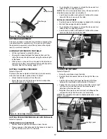
Figure 36 - Latches Lock and Unlock Blade Guard and Pawls
to Riving knife
Set Screws
Latches
Figure 37
Figure 38
Figure 39
Figure 40 - 3-Prong Receptacle
Grounding Prong
3-Prong Plug
Properly Grounded Outlet


