background image

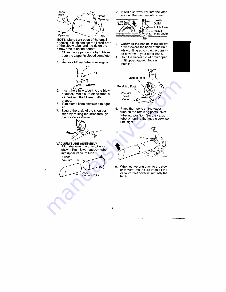
Elbow
Tube

Small
Opening

Dpper 

/

4

Opening Rib

NOTE: Make sure edge of the small
opening is flush against the flared area
of the elbow tube, and the rib on the
elbow tube is on the bottom.

3. Close the zipper on the bag. Make

sure the zipper is closed complete-
ly.

4. Remove blower tube from engine.

Rib

Groove

5. Insert the elbow tube into the blow-

er outlet. Make sure elbow tube is
aligned with the blower outlet
groove.

6. Turn clamp knob clockwise to tight-

en.

7. Secure the ends of the shoulder

strap by routing the strap through

the buckle as shown.

VACUUM TUBE ASSEMBLY

1. Align the lower vacuum tube as

shown. Push lower vacuum tube
into upper vacuum tube.

Upper
Vacuum Tube—.

Lower
Vacuum Tube

2. Insert a screwdriver into the latch

area on the vacuum inlet cover.

latch

Blower

Area

Outlet

– Latch Area

Vacuum

= Inlet Cover

3.

Gently tilt the handle of the screw-
driver toward the back of the unit

while pulling up on the vacuum in-

let cover with your other hand.

4.

Hold the vacuum inlet cover open

until upper vacuum tube is
installed.

Vacuu

Retaining Post

Vacuum

In let

Cover - .

5. Place the hooks on the vacuum

tube on the retaining posts; pivot
tube into position. Secure vacuum
tube by turning the knob clockwise
until tight.

When converting back to the blow-
er feature, make sure latch on the
vacuum inlet cover is securely fas-
tened.

-5-

Summary of Contents for 358.797290

Page 1: ...97290 WARNING Read and follow all Safety Rules and Operating Instructions before first use of this product 1 For answers to your questions about this product Call 7 am 7 pm Mon Sat or 10 am 7 pm Sun 1 800 235 5878 Hours listed are Central Time Sears Roebuck and Co Hoffman Estates IL 60179 U S A 530087632 7 12 00 ...

Page 2: ...il you completely understand and can follow all warnings and safety rules before operating the unit Restrict unit to users who under stand and will follow all warnings and safety rules in this manual PLAN AHEAD Always wear eye protection when op erating servicing or performing main tenance on unit Wearing eye protec tion will help to prevent rocks or debris from being blown or ricocheting into eye...

Page 3: ... Never place objects inside the blower tubes always direct the blow ing debris away from people ani mals glass and solid objects such as trees automobiles walls etc The force of air can cause rocks dirt or sticks to be thrown or to ricochet which can hurt people or animals break glass or cause other damage Never run unit without the proper equipment attached When using your unit as a blower always...

Page 4: ...standard screwdriver is required for assembly Service for the correct kit The spark arrestor blower tubes and nozzles must be assembled to unit to be in full compliance with regulations SPECIAL NOTICE Exposure to vibra tions through prolonged use of gasoline powered hand tools could cause blood vessel or nerve damage in the fingers hands and joints of people prone to cir culation disorders or abno...

Page 5: ...EMBLY 1 Align the lower vacuum tube as shown Push lower vacuum tube into upper vacuum tube Upper Vacuum Tube Lower Vacuum Tube 2 Insert a screwdriver into the latch area on the vacuum inlet cover latch Blower Area Outlet Latch Area Vacuum Inlet Cover 3 Gently tilt the handle of the screw driver toward the back of the unit while pulling up on the vacuum in let cover with your other hand 4 Hold the ...

Page 6: ...ING BLADES Your blower is equipped with mulching blades as a standard feature When using the optional vacuum attachment the mulching blades automatically reduce debris at a ratio of up to 16 1 Spark Plug Throttle Lever ON STOP AZ Primer Switch Button Fuel Mix Blower Choke Cap _ o Fill Tube Lever Starter Rope ON STOP SWITCH The ON STOP switch is used to stop the engine The switch stays in the ON po...

Page 7: ...such as gutters screens patios grills porches and gardens Watch out for children pets open windows or freshly washed cars Blow debris away safely Use the full blower nozzle exten sion so the air stream can work close to the ground After using blowers and other equipment CLEAN UP Dispose of debris in trash receptacles gine attempts to start move the choke lever to the HALF CHOKE position Once engin...

Page 8: ... grass etc could be picked up by the air intake and thrown out through the discharge opening damag ing the unit or property or causing seri ous injury to bystanders or the operator STARTING A COLD ENGINE or a warm engine after running out of fuel 1 Move the throttle lever to theft position 2 Move the choke lever to the FULL CHOKE position 3 Press the primer button slowly 12 times Throttle y Switch...

Page 9: ... unit does not cov er items that have been subjected to operator abuse or negligence To re ceive full value from the warranty the operator must maintain unit as instruct ed in this manual Various adjustments will need to be made periodically to properly maintain your unit CHECK FOR LOOSE FASTENERS AND PARTS Spark Plug Boot Air Filter Housing Screws CHECK FOR DAMAGED OR WORN PARTS Contact Sears Ser...

Page 10: ...l be per formed by your Sears Service Center CARBURETOR ADJUSTMENT Carburetor adjustment is critical and if done improperly can permanently damage the engine as well as the car buretor If you require further assis tance or are unsure about performing this procedure call our customer as sistance help line at 1 800 235 5878 Old fuel a dirty air filter a dirty fuel fil ter or flooding may give the im...

Page 11: ...ve in minimizing the formation of fuel gum deposits during storage Add stabi Mixture MIX Allow engine to idle Then accelerate the engine and note performance If engine hesitates bogs down or smokes during acceleration turn MIX screw clockwise in 1 16 turn incre ments until performance is satisfactory Repeat this procedure as necessary for proper adjustment After complet ng adjustments check for ac...

Page 12: ... 530015775 Screw 36 530095592 Clamp Blower Tube 10 530069983 Knob Replacement Kit 37 530049885 Knob Tube Clamp 11 530049495 Leadwire Switch 38 530095469 Handle 12 530049494 Wire Clamp 39 530049879 Muffler Cover Ass y 13 530069924 Carb Ass y Kit WA 229 40 530015880 Screw 14 530049496 Leadwire Ground 41 530069247 Line Kit Garb Purge 15 530052293 Choke Plate 42 530014362 Fuel Pick up Ass y 16 5304020...

Page 13: ...Impeller Ass y 38 530052266 Ignition Module 12 530095461 Mulch Blade Ass y 39 530016208 Bolt 13 530015828 Washer Flat 40 530016080 Screw Starter Pulley 14 530626605 Nut 41 530049903 Piston Ring 2 15 530049313 Inlet Door 42 530015162 Retainer 16 530402043 Spring Return Cover 43 530069945 Connecting Rod Ass y 17 530049297 Crankcase Cover 44 530069812 Piston Kit 18 530019 81 Gasket Crankcase Shroud I...

Page 14: ... 3 Gutter Attachment Kit 358 79997 6 1 3 2 l KEY NO PART NO DESCRIPTION 1 530095564 Vac Bag w Strap 2 530095470 Elbow Vac Tube 3 530095589 Lower Tube 4 530049686 Clip Vac Tube 5 530049485 Knob Vac Tube 6 530095468 Upper Tube I_ 3 3 _ LL 2 K EY NO PART NO DESCRIPTION 1 530094426 Nozzle 2 530402918 Elbow Spacer Ring 3 530094425 Extension Tube 4 530094424 Pivot Tube 5 952701645 Goggles 6 530094850 Ad...

Page 15: ...tates IL 60179 A ADVERTENCIA De no cumplir con todas las Reglas y Precauciones de Seguridad correra el riesgo de ac cidentes muy graves CONOZCA SU APARATO Lea el Manual del Usuario cuida dosamente hasta que comprenda perfectamente todas las adverten cias e instrucciones de seguridad y las pueda cumplir antes de poner el aparato en funcionamiento Limite el uso del aparato a aquel las personas que c...

Page 16: ...ionamiento Mantenga las superficies externs libres de aceite y de combustible Nunca ponga el motor en marcha ni lo deje en marcha dentro de un recintocerrado o en una area sin ventilation Respirar los vapores del combustible le podria causar la muerte Para evitar el choque por electrici dad estatica no use guantes de goma ni ningun otro guante aislado al usar el aparato No apoye el aparato con el ...

Page 17: ... estados incluyen do Californis Codigos de Recursos Publicos 4442 y 4443 Idaho Maine Minnesota Nueva Jersey Oregon y Washington Se requiere a ciertos mo tores de combustion interna operados en tierras cubiertas por bosques mator rales y o pasto en las area anterior mente rnencionadas que vengan equi pados con rejilla anti chispas mantenida en perfecto estado de funcionamiento o que el motor este c...

Page 18: ...ion con Ia ranura en Ia salida de aire del propulsor gire hasta encajar en su lugar AVISO La abrazadera del tubo debe ser aflojada lo suficiente que permitir al tubo de propulsion se introduzca en Ia salida de aire del propulsion Aflojar Ia abrazadera del tubo gire Ia perilla ha cia Ia izquierda Salida de Aire g 4del Propulsion Tubo de Propulsion Ranura Moldura saliente 2 Apriete Ia abrazadera del...

Page 19: ...ada de aire del aspirador abierta hasta que el tubo de aspiration quede instalado Entrada de Aire del Aspirador f Poste de Retention Compuerta de entrada de aire 5 Coloque los ganchos que se en cuentran en el tubo de aspiracion en el poste de retencion gire el tubo hasta quedar en posicion Asegure el tubo de aspiracion gi rando la perilla hacia Ia derecha hasta quedar ajustado hos 6 Al volver a co...

Page 20: ...l interruptor debera estar en la posicion ON para hacer arrancar el motor Para parar el motor presione y sostenga el interrputor hasta que el motor se detenga PALANCA DEL ACELERADO El PALANCA DEL ACELERADO controla Ia velocidad del motor Muevalo com pletamente hacia adelante para maxi ma velocidad Muevalo completa mente hacia atras para conseguir Ia marcha lenta BOTON DEL BOMBEADOR El BOTON DEL BO...

Page 21: ...y puertas patios asadores a la parrilla balcones y jardines Tenga cuidado con los ninos ani males domesticos ventanas ab er tas y carros recien lavados Sople los escombros con precaucidn Use la extension completa de la bo quilla del propulsor para que la cor riente de aire pueda trabajar cerca del suelo Despues de usar los proputsores de aire y otro tipo de equipo LIMPIE Deseche los escombros en r...

Page 22: ...nas animales vidrieras y otros objetos solidos e A ADVERTENCIA Al arrancar el motor sostenga el aparato como se ilustra en Ia figura Apoye el aparato exclusivamente en una superficie lim pia y solida siempre que vaya a efec tura el arranque y siempre que tenga que apoyar el aparato con el motor en marcha Los escombros tales como gravilla arena tierra cesped etc pueden ser succionados por Ia entra ...

Page 23: ...cada uso Verificar que no haya piezas danadas o gastadas Antes de cada uso Limpiar el aparato y sus placas Despues de cada uso Limpiar el filtro de aire Cada 5 horas de uso Cambie la bujia Anualmente Cambie el filtro del combustible Anualmente Verifique los tornillos del silenciador Anualmente 46 ADVERTENCIA Detenga el motor y asegurese de que las cuchil las del impulsor no se encuentren gi rando ...

Page 24: ...ma el filtro para distribuir el aceite 6 Reponga las piezas CAMBIE LA BUJIA Cambie Ia bujia anualmente La sepa racion de los electrodos de Ia bujia deberfi ser de 025 de pulgada El en cendido es fijo y no es ajustable 1 Gire y luego retire Ia capucha de la bujia 2 Retire Ia bujia del cilindro y dese chela 3 Cambiela por una bujia RCJ 8Y y ajust ela con una Have de 3 4 de pulgada 4 Vuelva a instala...

Page 25: ...reloj hasta que se pare 2 Gire el tornillo de marcha lenta a la derecha en el sentido del reloj hasta que se detenga Seguida mente girelo hacia Ia izquierda 4 vueltas y media 3 Ponga el motor en marcha y dejelo en marcha por 3 minutos Luego proceda a ajustar los tornillos de acuerdo a las instrucciones indicas en la siguiente section Si el funcio namiento del motor es aceptable con las posiciones ...

Page 26: ...r Los estabilizadores de combustible son una alternativa acept able para minimizar Ia formaci6n de los depositos de goma durante el al macenaje Anada estabilizador a Ia ga solina en el tanque de combustible o en el recipiente para alacenaje de combus tible Siga las instrucciones de mezcla que se encuentran en Jos envases del estabilizador Ponga el motor en marcha y dejelo en marcha por to menos 5 ...

Page 27: ...ars 3 La compresion ester baja 3 Entre an contacto con el Servicio Sears El motor no I El filtro de aire ester sucio 1 Limpie o cambie el filtro de aire acelera le 2 La bujia esto 2 Limpie o cambie la bujia y calibre falta carbonizada Ia separacion potencia o 3 El carburador requiere 3 Vea la seccion Servicio y Ajustes se pars bajo ajuste carga 4 Acumulacion de Carbon 4 Entre an contacto con el Se...

Page 28: ...a pieza del mismo ha fallado de bido al abuso negligencia mantenimi ento no apropiado modificaciones sin aprobacion o el use de piezas que no han sido hechas o aprobadas por el fbricante original del equipo Usted sera el responsable de pre sentar el motor del equipo de cesped y jardin a un centro de reparaciones autorizado Sears tan pronto como surjaa el pro blema Las reparaciones bajo ga rantia d...

Page 29: ...o autorizado mas cercano o Ilamar a Sears at 1 800 473 7247 EN DONDE OBTENER SERVICIO DE GARAN TIA Servicio o reparaciones de ga rantia debera ser provistas por todos los centros de servicio Sears flame al 1 800 473 7247 MANTENIMIENTO REEMPLAZO Y REPARACIONES DE PIEZAS RELACIONADAS CON LA EMISION Cualquier pieza de reempla zo Sears aprobada usada en Ia pro gramacion de cualquier mantenimiento de g...

Page 30: ...accessories and owner s manuals that you need to do it yourself call Sears PartsDirect I 1 800 366 PART 6 a m 11 p m CST 1 800 366 7278 7 days a week www sears comlpartsdirect To purchase or inquire about a Sears Service Agreement 1 800 827 6655 7 a m 5 p m CST Mon Sat Para pedir servicio de reparaci6n a domicilio Au Canada pour service en francais y para ordenar piezas con entrega a domicilio 1 8...

Page 31: ...anty rights and responsibilities you should contact your nearest authorized ser vice center or call Sears at 1 800 473 7247 WARRANTY PE RIOD Any warranted part which is not scheduled for replacement as required maintenance or which is scheduled only for regular inspection to the effect of repair or replace as necessary shall be warranted for 2 years Any warranted part which is scheduled for replac...

Page 32: ...530015820 Bolt 9 530015775 Screw 36 530095592 Clamp Blower Tube 10 530069983 Knob Replacement Kit 37 530049885 Knob Tube Clamp 11 530049495 Leadwire Switch 38 530095469 Handle 12 530049494 Wire Clamp 39 530049879 Muffler Cover Ass y 13 530069924 Carb Ass y Kit WA 229 40 530015880 Screw 14 530049496 Leadwire Ground 41 530069247 Line Kit Garb Purge 15 530052293 Choke Plate 42 530014362 Fuel Pick up ...

Reviews: