background image

Summary of Contents for 390.2514

Page 1: ...Instructions Before FirstUse of This Product Save ThisManual For Future Reference I RRFTSMRN PROFESSIONAL HYDROGLASS SHALLOW WELL JET PUMP Safety Instructions Installation Operation Troubleshooting Repair Parts Sears Roebuck and Co Hoffman Estates IL 60179 U S A PRINTED IN USA Form No F642 04073 8 3 o4 ...

Page 2: ...ing instruc tions in this manual when connecting mo tot to power lines Make workshops childproof use padlocks and master switches remove starter keys General Safety Do not allow pump pressure tank piping or any other system component containing water to freeze Freezing may damage sys tem leading to injury or flooding Allowing pump or system com ponents to freeze will void warranty General Safety W...

Page 3: ...d your pump will not work to its full rated capacity If in doubt contact your local Power Company 3 Be certain your pump installation meets all local plumbing pump and well codes 4 While installing the pump always keep the well covered to pre_ vent leaves and foreign matter from falling into the well and con taminating the water and or causing possible serious damage to the mechanical operation of...

Page 4: ... 2 Be sure the vertical distance lift from the priming level to pump is not over 20 feet if the pump is over well This will be less if pump is offset from the well Both figures are for sea level The maximum lift of any pump decreases with the elevation above sea level This decrease is at the rate of 1 foot per 1000 feet of eleva tion For example the lift is 17 feet and your elevation is 3000 feet ...

Page 5: ... above also shows the pressure switch If the power supply connection still needs to be made the pressure switch cover will need to be removed Your motor terminal board located under the motor end cover should look like the one at right Figure 5 Voltage Set To 230 Volts Dial Type To change to I 15 volts 1 Make sure power is off 2 Tuna the dial counter clockwise until 115 shows in the diai window 3 ...

Page 6: ... copper ground wire to the green ground screw 3187 0398 FIGURE 6 Pressure switch wiring Connection Procedure 1 Connect the ground wire first as shown in Figure 9 The ground wire must be a solid copper wire at least as large as the power supply wires 2 There must be a solid metal connection between the pressure switch and the motor for motor grounding protection If the pressure switch is not connec...

Page 7: ... DO NOT USE PIPE JOINT COMPOUND 1 Wrap 1 1 2 to 2 turns of Teflon tape to all male pipe threads being attached to the pump This will insure leakproof connec tions Do not overtighten threaded fittings in the plastic pump If leaks do occur remove the fitting replace the Teflon tape and rewrap with 1 1 2 to 2 turns of Teflon tape and remake the connection 2 Independently suppo_ all piping connected t...

Page 8: ... side with plastic mallet This will insure proper seating of O Ring and clamp E Assemble base mounting bolts Connect pressure switch tub ing and close draincock F Prime pump and turn on power REMOVING MOTOR FOR SERVICE AND REPLACING SHAFT SEAL flit is necessary to remove motor always replace the shaft seal We suggest you purchase this item U109 6A and have it on hand for future use NOTICE The seal...

Page 9: ...ell Jet To remove debris from venturi or nozzle proceed as follows 1 Disassemble pump per instructions on Page g 2 Turn venturi counterclockwise and remove it The nozzle is now exposed Remove it using a 5 8 hex socket wrench with extension Turn counterclockwise If socket wrench is not avali able insert an ice pick or similar pointed tool careflflly into the nozzle This will dislodge debris 3 Flush...

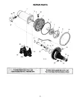
Page 10: ...REPAIR PARTS 29 28 I 1 26 2 3 3A 7 8 lO 25 25A 23 766 1194 22 21 19 20 0 ...

Page 11: ...C Motor 1 2 HP 115 230V 60 Cycle Motor 3 4 HP 115 230V 60 Cycle Water Slinger Reducer Bushing 1 2 x 1 8 NPT Pipe Plug 1 8 NPT Tank Body Back Half O Ring Sq Cut Tank Body 9 1 2 x 9 x 1 4 Shaft Seal Impeller Diffuser Screw 8 32 x 7 8 5 Required 8 Star Washer 5 Required Clamp Tank Body O Ring Venturi 1 3 8 x 1 1 8 x 1 8 Venturi Nozzle Insert Gasket Tank Body Assembly Front Half Includes Key No 11 12 ...

Page 12: ...ptive Tank Model 390 2514 and Model 390 2518 require 40 pounds for proper operation 1 Pump is picking up prime 2 Leak in suction side of pump 3 Well is gaseous 4 Intermittent over pumping of well 1 Loose clamps or O Ring not sealed a Re prime according to instructions b Check all connections on suction line air volume control and jet c Replace foot valve 2 In installation already in use a Check al...

Page 13: ...13 ...

Page 14: ...14 ...

Page 15: ...15 ...

Page 16: ...e repair orreplacementpartsyouneed Call 7 am 7 pro 7 daysa week 1 800 366 PART 1 800 366 7278 ForIn homemajor brandrepair service Call 24 hours a day 7 daysa week 1 800 4 REPAIR 1 800 473 7247 Forthe locationof a gearsRepairServiceCenterinyourarea Call24 hours a day 7 daysa week 1 800 488 1222 For informationonpurchasing a Sears MaintenanceAgreementorto inquire aboutan existingAgreement call g am ...

Reviews: