background image

Summary of Contents for 486.241320

Page 1: ...ead Rules for Safe Operation and Instructions Carefully 32 CRAFTSMAN LAWNSWEEPER o Assembly Operation o Customer ResponsibiSities Repair Parts Sears Roebuck and Co Hoftman Estates IL 60179 U S A PR1NTED IN U S A ...

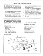
Page 2: ...ways 7 Keep all nuts bolts and screws tight to be sure equipment is in safe working condition 8 Vehicle and attachments should be stopped and inspected for damage after striking a foreign object and damage should be repaired before restarting and operating the equipment 9 Fo low maintenance instructions as outlined in this manual Your lawnsweeper carton and inner pack parts carton contains parts a...

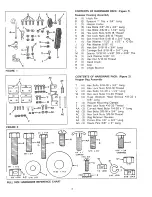
Page 3: ... O D x 3 16 Thk Lock Washer 5 t6 t D Hex Nut 5 16 8 Thread Hand Knob Grip Angle Bracket Y X AC FIGURE 2 AG CONTENTS OF HARDWARE PACK Figure 2 Hopper Bag Assembly T 4 Hex Bolts 5 16 18 x 3 4 Long U 4 Hex Lock Nuts 5 16 t8 Thread V 2 Hex Bolts 1 4 20 x 1 1 4 Long W 4 Hex Lock Nuts 1 4 20 Thread X 4 Truss Slotted Head Screws 10 32 x 5 8 Long Y 4 Hopper Mounting Clamps Z 4 Hex Lock Nuts 10 32 Thread A...

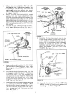
Page 4: ...ASHER SWEEPER HOUSING FIGURE 4 NOTE Before assembling the hitch bracket to the hitch tongue refer to figure 5 and page 11 to determine which position is required for your towing vehicle SWEEPER HOUSING 5 16 x 1o112 CARRIAGE BOLT HITCH TONGUE 5116 FLAT WASHER 5f16 HEX LOCK NUT FIGURE 3 Attach the brace rod to the square hole in the sweeper housing using two 5 16 x 3 4 carriage bolts assembled with ...

Page 5: ...he angle bracket See figure 7r Place spacer over end of 5 16 x 3 4 slot head bolt and into large hole on strap Assemble threaded end of slot head bolt through hole in the angle bracket and secure with 5 16 lock washer and 5 16 hex nut See figure 7 Assemble other end of height adjustment strap to height adjustment handle See figure 7 Place slot on strap in line with square hole in height adustment ...

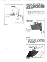
Page 6: ...tube through the hopper bag stitched flaps starting at the center cut out in the top of the hopper bag See figures 10 11 and 12 Repeat for the right hand upper hopper tube CENTER CUT OUT START UPPER HOPPER TUBE LEFT HAND SHOWN BAG FLAP I FIGURE 10 2 Locate the hole on side of both upper hopper tubes See figure 11 The bag wi l require piercing at these holes in a later step Refer to step 12 on page...

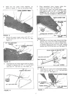
Page 7: ...upper and lower hopper tube ends together with two 3 8 x 3 4 hex bolts inside and 3 8 hex lock nuts outside See figure 15 Do not overtighten to allow for pivot UPPER HOPPER TUBE 3f8 HEX LOCK NU3 OUTSIDE HOPPER TUBE HOPPER BAG _ 318 x 3f4 HEX BOL INSIDE FIGURE 15 8 Assemble the bag frame strap bottom and bag retainer top to the front edge of bag bottom Place the bag retainer on top and frame strap ...

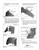
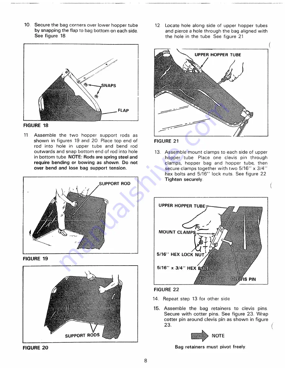
Page 8: ...teel and require bending or bowing as shown Do not over bend and lose bag support tension_ R i ROD UPPER HOPPER TUBE FIGURE 21 13 Assemble mount clamps to each side of upper hopper tube Place one clevis pin through clamps hopper bag and hopper tube then secure clamps together with two 5 6 x 3 4 hex bolts and 5 16 lock nuts See figure 22 Tighten securely UPPER HOPPER TUBE MOUNT CLAMPS FIGURE 19 FIG...

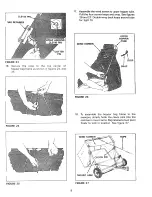
Page 9: ...OTTER PIN FIGURE 23 16 Secure the rope to the top center of hopper bag frame as shown in figures 24 and 25 FIGURE 24 WIND SCREEN UPPER HOPPER LOOP SNAP FIGURE 26 t To assemble the hopper bag frame to the sweeper simply hook the clevis pins into the notches in mount arm Bag retainers must pivot freely to lock in position See figure 27 WIND SCREEN ROPE MOUNT ARM FIGURE 25 FIGURE 27 9 ...

Page 10: ...19 To remove the hopper bag frame from the sweeper simply flip the bag retainers upward and remove the bag See figure 28 J J HOPPER MOUNT ARM BAG RETAINER FIGURE 28 0 ...

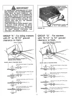
Page 11: ...29 ITH BRUSH HEIGHT SETTINGS IOXIMATELY APPROXIMATELY LEVEL OR 3 TO 4 OFF SURFACE GROUP A For riding mowers with 8 to I0 1 2 ground cDearance to hitch HITCH TONGUE WITH HITCH BRACKET MOUNTED BELOW HITCH TONGUE BLACK LINE IS TRACTOR HITCH T WO SPACERS ABOVE TRACTOR H ONE SPACER ABOVE AND BELOW TRACTOR HITCH TWO SPACERS BELOW TRACTON HITCH i TWOSPACERS AND HITCH BAR _ BELOW TRACTOR HITCH Vf t T 3 I ...

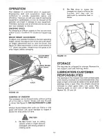
Page 12: ... too close to a fire as the brushes and bag can be destroyed by excessive heat or flame ROPE 4 SH ADJUSTMENT ASS y TO RAISE BRUSH Push Do wn KNOB I FIGURE 30 FIGURE 31 STORAGE The bag may be collapsed for storage Remove the two support rods and fold bag down LUBRHCATION CUSTOMER RESPONSRBHLITHES The bearings in the sweeper have been prelubricated at the factory however it is recommended that a few...

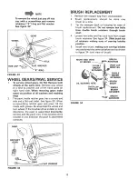
Page 13: ...s assembled incorrectly remove and flip pawl over If the brushes drive rotate in one direction the pawi is assembled correctly_ PAWL _ 1 BRUSH REPLACEMENT 1 Remove the hopper bag from lawnsweeper_ 2 Brush replacement should be done one brush at a time 3 Tip the sweeper back on housing for ease of brush replacement Do not remove hex bolts from double brush retainers through brush shaft 4 Loosen hex...

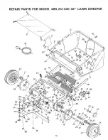
Page 14: ...REPAIR PARTS FOR MODEL 486 241320 32 LAWN SWEEPER 9 45 t2 1o 52 80 42 23 48 2 3 3 45 _ 84 52 64 1I 18 41 75 65 6O t 60 18 4 7 14 i 72 t _ 9 J 2_ 81 22 20 17 4O 24 41 20 19 3 15 17 14 ...

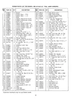
Page 15: ...olt 1 4 20 x 3 4 Lg 77 Gr_ 5 78 Curved Hd_ Bolt 5 16 18 x 79 1 5 8 Angle Bracket 80 Brush Shaft 81 Brush Retainer Double 82 Brush Retainer Single Wheel Ass y Comp 83 Skirt Retainer 84 Lockwasher 5 16 I D 85 Grip 86 Hub Cap Hitch Bracket REE NO PART NOo 48 23812 49 23351 50 43926 51 1671 t 52 43346 43662 Rt9 3 316 43064 43182 43013 43513 43407 43082 509 90 0 t 42 000 i 43978 23331 23868 23354 43681...

Page 16: ... lubricated according to the operating and maintenance instructions in the owner s manual Sears will repair free of charge any defect in material or workmanship This warranty does not cover repairs necessary because of operator abuse or negligence including the failure to maintain the equipment according to instructions contained in the owner s manual and Lawnsweeper used for commercial or rental ...

Reviews: