background image

13

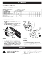
SPROCKET, CHAIN AND PAWL SERVICE

IMPORTANT: Do not remove both wheels at the same 
time to avoid mixing of parts. (The R.H. and L.H. ratchet 
sprockets are not interchangeable.) 

Make notes on the 

position of washers and snap rings during disassembly.

•  Remove the dust cover by removing the two rivets 

which fasten it to the wheel housing. (It is not 
necessary to remove the dust cover if you are only 
cleaning and lubricating the chain and sprockets.)

•  Remove the retaining rings and washers which hold 

the sprockets onto the shafts.

•  Remove the chain and both sprockets, holding them in 

position and sliding them off both of the shafts. (Look 
for the drive pin, which may fall out of the brush shaft 
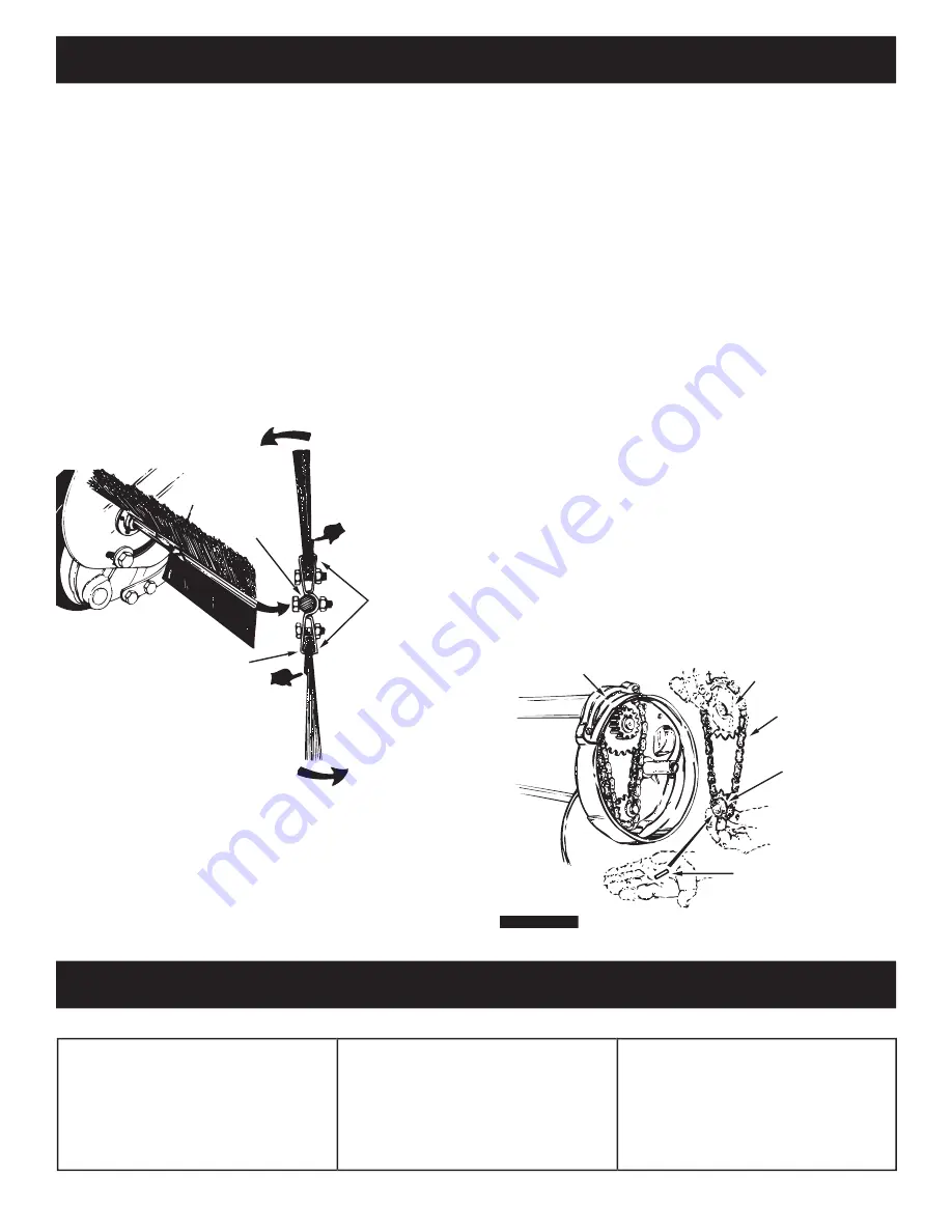
when the ratchet sprocket is removed.) See fi gure 24.

•  To reassemble, insert the drive pin through the hole 

at the end of the brush shaft. Make sure the pin slides 
back and forth easily in the shaft.

•  Lightly grease both shafts and the chain, and fi ll the 

ratchet sprocket with grease. Assemble the chain with 
both sprockets back onto the shafts.

•  Lightly grease the axle and then reassemble the wheel.  

The brushes should rotate 

only during forward rotation 

of the wheel. If the brushes are driven (rotated) by both 
forward and reverse rotation of the wheel, the drive pin 
is jamming in the ratchet gear. Disassemble and clean 
and lubricate the drive pin and ratchet gear.

BRUSH REPLACEMENT

NOTE:  Brush replacement should be done one brush at  


a time.

•  Remove the hopper bag from the sweeper.
•  Loosen the hex bolts and lock nuts on two single 

brush retainers which clamp one brush to the double 
brush retainers. 

Do Not loosen or remove the bolts 

which fasten the double brush retainers to the brush 
shaft. See fi gure 23.

•  Slide the brush out of the retainers, noting on which 

side of the brush the bristles overlap. See fi gure 23.

•  Install new brush, making sure the bristles overlap on 

the same side of the brush as before. See fi gure 23.

GEAR SPROCKET

CHAIN

RATCHET
SPROCKET

DRIVE PIN

DUST COVER

BRUSH ROTATION      

BRUSH ROTATION

OVERLAP
BRISTLES

OVERLAP
BRISTLES

SINGLE
BRUSH
RETAINERS

DOUBLE BRUSH RETAINER

BRUSH
 SHAFT

FIGURE 23

•  Brushes set too low.

•  Brushes are jammed
•  Wheels are jammed.

Wheels skid when sweeping.

•  Adjust  height  till  brushes  are  1/2" 

down into grass.

•  Stop sweeper. Remove obstruction.
•  Remove one wheel at a time to check 

for obstruction or damage. Refer  to 
Service and Adjustments section.


SERVICE AND ADJUSTMENTS

TROUBLESHOOTING

Summary of Contents for 486.24222

Page 1: ...ct read this manual and follow all Safety Rules and Operating Instructions Safety Assembly Operation Maintenance Parts PRINTED IN U S A FORM NO 49997 12 05 Sears Roebuck and Co Hoffman Estates IL 60179 U S A www sears com craftsman IMPORTANT For Missing Parts or Assembly Questions Call 1 866 576 8388 ...

Page 2: ... reduced speed on rough terrain near ditches and on hillsides to prevent loss of control 6 Vehicle braking and stability may be affected with the attachment of this sweeper Do not fill sweeper to maximum capacity without checking the capability of the towing vehicle to safely pull and stop with the sweeper attached Stay off of steep slopes 7 Stop and inspect vehicle and sweeper for damage after str...

Page 3: ...3 12 13 ACCESSORIES AND ATTACHMENTS TheFrontMountDethatcher Model486 24219attaches to the lawn sweeper to help loosen and remove dead grass and thatch from the lawn while sweeping These accessories were available when the unit was purchased They are also available at most Sears retail outlets and service centers Most Sears stores can order repair parts for you when you provide the model numbers of...

Page 4: ...5 16 18 x 1 3 4 Lg D 1 Carriage Bolt 5 16 18 x 1 Lg E 4 Carriage Bolt 5 16 18 x 3 4 Lg F 12 Nylock Nut 5 16 G 2 Palnut 3 8 H 1 Flat Washer 5 16 Standard I 1 Washer Tooth Lock 5 16 J 2 Hitch Spacer 3 4 REF QTY DESCRIPTION K 1 Spacer Bushing L 1 Hairpin Cotter 1 8 M 8 Hairpin Cotter 3 32 N 2 Clevis Pin 3 8 x 1 2 O 4 Clevis Pin 1 4 x 1 1 8 P 2 Clevis Pin 1 4 x 1 3 4 Q 4 Hopper Clamp R 4 Plastic Plug ...

Page 5: ...ts lay them on cardboard or a mat Remove the sweeper housing the loose parts and the hardware package from the carton Lay out the parts and hardware as shown on pages 3 and 4 10 STEP 2 ASSEMBLE HITCH TUBES The hitch tubes are stamped with a 77L for the left tube and a 76R for the right tube The sweeper housing is marked with and L on the left with side and an R on the right side See figure 1 Hold t...

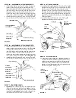
Page 6: ...adjustment handle as shown in figure 5 FIGURE 4 STEP 6b ASSEMBLE HITCH BRACKETS If the tractor hitch is 10 or more above the ground place the bent hitch bracket on top of the hitch tubes and place the hitch bracket assembly underneath the hitch tubes Insert two hex bolts B through the brackets with the rear hex bolt between the cross bolts in the hitch tubes Secure the hex bolts B with two nylock n...

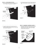
Page 7: ...an face up FIGURE 8 FIGURE 10 LOWER HOPPER TUBE HOPPER BAG BOTTOM UPPER HOPPER TUBE CLEVIS PIN N HAIR COTTER PIN M UPPER HOPPER TUBE PLASTIC PLUG R REAR HOPPER TUBE LOWER HOPPER TUBE PLASTIC PLUG R REAR HOPPER TUBE CLEVIS PIN O HAIR COTTER PIN M STEP 12 ASSEMBLE TUBES TO BAG Unfold the hopper bag reverse the fold of the mesh wind screen and then lay the bag out flat with the wind screen on top Inse...

Page 8: ...g the snaps See figure 13 FIGURE 13 STEP 13 ATTACH BAG BOTTOM Insert the bag frame strap into the stitched sleeve at the front edge of the bag bottom See figure 11 FIGURE 12 FIGURE 14 CLEVIS PIN O HAIR COTTER PIN M BAG FRAME STRAP SNAP FLAP BAG FRAME STRAP STITCHED SLEEVE Assemble the bag frame strap to the holes in the lower hopper tubes using two clevis pins O and hair cotter pins M See figure 12 F...

Page 9: ... hopper tube as shown in figure 18 FIGURE 19 Assemble a vinyl cap S onto each bag arm tube as shown in figure 17 Assemble two palnuts G onto the ends of the pivot rod using a hammer See figure 17 HINT To ease assembly of the palnuts place the bag on its side on a solid surface With the bottom end of the pivot rod against the surface tap a palnut onto the top end of the rod Repeat for other end of rod...

Page 10: ...to the tractor hitch arranging the 3 4 spacers in one of six possible combinations as shown in GROUP A and GROUP B diagrams below IMPORTANT To obtain the best performance from your sweeper arrange the spacers so that the sweeper bag is approximately level with the ground and approximately 5 to 7 off the ground as shown in figure 20 GROUP B For vehicles with hitches having 10 to 13 ground clearance ...

Page 11: ... grass to an even height before sweeping SWEEPING SPEED Try a starting speed of approximately 3 m p h third gear on most tractors Depending on the conditions it may be necessary to adjust the sweeping speed in order to achieve best results OPERATION Hopper Bag Collects grass clippings leaves and debris Hopper Rope Permits dumping of hopper bag from driver s seat Windscreen Helps prevent collected ...

Page 12: ...with an even coat of light grease To remove the wheel pop off the hub cap using a screwdriver and remove the lock nut and flat washer See figure 22 CLEANING Clean sweeper housing with a soft brush or cloth Clean debris from hopper bag with a brush or broom Remove any material which has wrapped around brushes or ends of brush shaft CUSTOMER RESPONSIBILITIES Read and follow the maintenance schedule an...

Page 13: ...e only during forward rotation of the wheel If the brushes are driven rotated by both forward and reverse rotation of the wheel the drive pin is jamming in the ratchet gear Disassemble and clean and lubricate the drive pin and ratchet gear BRUSH REPLACEMENT NOTE Brush replacement should be done one brush at a time Remove the hopper bag from the sweeper Loosen the hex bolts and lock nuts on two sin...

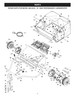
Page 14: ...40 14 81 34 79 22 37 21 37 20 64 76 75 28 2 11 12 13 59 33 81 7 5 4 52 61 63 66 60 49 58 59 68 51 50 69 57 67 65 62 59 1 9 27 8 9 10 32 6 3 80 78 77 28 70 59 83 75 43 42 44 48 45 72 73 75 75 71 71 44 72 70 54 74 46 53 46 53 82 74 42 44 43 REPAIR PARTS FOR MODEL 486 24222 42 HIGH PERFORMANCE LAWNSWEEPER ...

Page 15: ... 8 Lg 7 44947 2 Bolt Cvd Hd 5 16 18 x 1 5 8 Lg 7 44947 2 Bolt Cvd Hd 5 16 18 x 1 5 8 Lg 7 44947 2 Bolt Cvd Hd 5 16 18 x 1 5 8 Lg 8 44695 2 Washer Bowed 1 x 32 x 06 8 44695 2 Washer Bowed 1 x 32 x 06 8 44695 2 Washer Bowed 1 x 32 x 06 8 44695 2 Washer Bowed 1 x 32 x 06 8 44695 2 Washer Bowed 1 x 32 x 06 9 43086 6 Lock Washer 5 16 9 43086 6 Lock Washer 5 16 9 43086 6 Lock Washer 5 16 9 43086 6 Lock ...

Page 16: ...l installation of home appliances and items like garage door openers and water heaters 1 800 4 MY HOME 1 800 469 4663 Call anytime day or night U S A and Canada www sears com www sears ca Our Home For repair of carry in items like vacuums lawn equipment and electronics call or go on line for the location of your nearest Sears Parts Repair Center 1 800 488 1222 Call anytime day or night U S A only ...

Reviews: