background image

8

Call 1-866-576-8388 for missing parts or assembly help 

DO NOT RETURN TO STORE

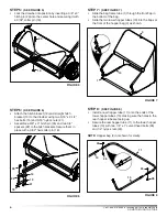
sTep 13:  

(see FigUre 13)

Secure the top and bottom hopper tubes together 

1. 

using two 5/16" x 3/4" hex bolts (17) on inside and 
two 5/16" nylock nuts (21) outside.

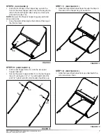
sTep 14:  

(see FigUre 14)

Install two cotter pins (27) in the rear hopper tube. 

• 

Bend ends of cotter pins around tube. 
Slide the dump handle clip (33) onto the dump handle.

• 

Attach the dump tube to the rear hopper tube using a 

• 

U-clamp (34) placed between the cotter pins, a 1/4" x 
1-1/2" hex bolt (16) and a 1/4" nylock nut (24). 
Swivel the dump tube so that the end of the tube 

• 

rests on the ground behind the bag and supports the 
rear of the bag in an upright position.

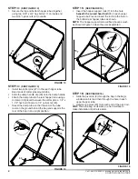
sTep 15:  

(see FigUre 15)

Insert the hopper support rods (7) into the hole 

• 

beneath the curved head bolt

 (26) in each upper 

hopper tube. Flex and insert the rod into the hole in 
the bottom rear hopper tubes as shown.

NOTe: 

The hopper support rods will flex about as much 

as shown in figure 15 when they are assembled.

sTep 16:  

(see FigUre 16)

Slide the pivot rod (2) through the flap in the bag's 

• 

windscreen first and then through the hole in each 

upper hopper tube.
Hammer a palnut (23) onto each end of the pivot rod . 

• 

HiNT: 

Place the bag on its side on a hard surface to 

make installation of palnuts easier.

FigUre 13

17

17

21

21

FigUre 14

24

27

16

34

5

33

FigUre 15

7

7

26

7

FigUre 16

2

23

Summary of Contents for 486.24229

Page 1: ... Roebuck and Co Hoffman Estates IL 60179 U S A www sears com craftsman CAUTION Before using this product read this manual and follow all Safety Rules and Operating Instructions Safety Assembly Operation Maintenance Parts STOP DO NOT RETURN TO STORE For Missing Parts or Assembly Questions Call 1 866 576 8388 ...

Page 2: ...rvice back page CRAFTSMAN FULL WARRANTY When operated and maintained according to all supplied instructions if this Craftsman product fails due to a defect in material or workmanship within one year from the date or purchase return it to any Sears store or other Craftsman outlet in the United States for free replacement This warranty applies for only 90 days from the date of purchase if this produ...

Page 3: ...ll and stop with the sweeper attached Stay off of steep slopes Do not exceed 6 m p h Driving too fast may cause damage to sweeper s wheels and bearings Do not hold onto dump handle while tractor is moving Never attach dump handle to tractor or any part of your body Always keep it secured to the hopper bag while tractor is moving If any part of dump handle should become damaged stop use of sweeper ...

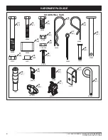
Page 4: ...ware package 44292 43648 43182 43343 47810 44917 23368 47189 712 3046 7071 26484 712 0421 41036 43978 43093 43055 47623 48365 41013 23353 23878 15 x7 16 x1 17 x4 24 x6 18 x1 27 x2 26 x5 19 x3 28 x2 20 x1 32 x2 31 x2 33 x1 34 x1 35 x1 29 x1 30 x2 25 x2 21 x9 22 x2 23 x2 shown full size ...

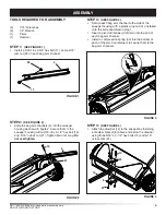
Page 5: ...ut 21 Tighten bolt until snug Do not overtighten STEP 3 SEE FIGURE 3 Secure each bag arm channel to the side of the sweeper housing with a plastic wing nut 31 installed onto the bolt assembled in step 1 Insert a pivot rod retainer 30 down into the end of each bag arm channel Install a compression spring 32 into the bottom of each of the pivot rod retainers to secure them to the bag arm channels fi...

Page 6: ...spacers 22 to the hitch brackets Secure them in place with a 3 32 hair cotter pin 18 21 13 12 15 35 22 18 STEP 7 SEE FIGURE 7 Slide the bag frame tube 1 through the front flap in the bottom of the bag Slide the two lower hopper tubes 10 into the flaps at the front of the hopper bag 3 as shown figure 8 STEP 8 SEE FIGURE 8 Install a rear hopper tube 11 onto the ends of the lower hopper tubes 10 maki...

Page 7: ...ides of the bag to the bottom of the bag at the front corners figure 10 STEP 10 SEE FIGURE 10 Slide a rear hopper tube 11 onto the two upper hopper tubes 6 Secure the upper hopper tubes 6 to the rear hopper tube 11 using two 1 4 x 1 curved head bolts 26 and 1 4 nylock nuts 24 Bolt heads should face up STEP 11 SEE FIGURE 11 Slide the assembled tubes down through the flaps in the sides of the hopper...

Page 8: ...nd of the tube rests on the ground behind the bag and supports the rear of the bag in an upright position STEP 15 SEE FIGURE 15 Insert the hopper support rods 7 into the hole beneath the curved head bolt 26 in each upper hopper tube Flex and insert the rod into the hole in the bottom rear hopper tubes as shown NOTE The hopper support rods will flex about as much as shown in figure 15 when they are...

Page 9: ...re 20 Arrange the spacers into one of the three possible 4 combinations as shown below in the GROUP A GROUP B and GROUP C diagrams in figure 20 IMPORTANT To obtain the best performance from your sweeper arrange the spacers so that the sweeper bag is approximately level with the ground as shown in figure 19 APPROXIMATELY LEVEL BRUSH HEIGHT ADJUSTED APPROXIMATELY MID WAY figure 19 GROUP B VEHICLES W...

Page 10: ...ever to raise the brush or push up on the lever to lower the brush See figure above Best adjustment is when the brush setting is 1 2 down into the grass Always mow the grass to an even height before sweeping CAUTION Keep sweeper away from fire Excessive heat can damage the brushes and hopper bag and could cause the bag and its contents to burn DUMPING OF SWEEPER Your sweeper can be dumped without ...

Page 11: ...ubricate the brush shaft bearing twice a with a few drops of light weight oil Every two years remove wheels and clean sprockets chains and gears found inside the wheel housing After cleaning lubricate with an even coat of light grease To remove the wheel pop off the hub cap using a screwdriver and remove the lock nut and flat washer Cleaning Clean sweeper housing with a soft brush or cloth Clean d...

Page 12: ...cleaning and lubricating the chain and sprockets Remove the retaining rings and washers which hold the sprockets onto the shafts Remove the chain and both sprockets holding them in position and sliding them off both of the shafts Look for the drive pin which may fall out of the brush shaft when the ratchet sprocket is removed See figure 22 To reassemble insert the drive pin through the hole at the...

Page 13: ...13 Call 1 866 576 8388 for missing parts or assembly help DO NOT RETURN TO STORE NOTES ...

Page 14: ...19 30 30 32 32 8 8 37 36 53 75 38 53 75 7 7 11 26 26 26 24 16 34 26 26 24 24 24 24 24 11 27 2 23 23 4 10 10 5 6 6 4 28 28 15 15 20 15 15 66 65 62 76 63 71 64 39 15 21 21 18 12 22 13 14 15 35 21 21 19 31 31 25 25 56 57 60 61 24 59 55 55 72 70 41 42 70 69 68 50 73 74 48 49 47 43 21 45 45 52 46 54 51 52 54 51 17 17 17 21 21 17 3 29 9 33 40 58 77 77 ...

Page 15: ...1 66413 Height Adjustment Tube 38 1 40891 Height Adjustment Knob 39 1 66656 Wheel Housing RH ref qty part no description 40 1 66657 Wheel Housing LH 41 2 1650 1 Retaining Ring E Type 42 2 716 0106 Retaining Ring 5 8 E Type 43 4 736 0231 Washer 344 x 1 125 x 12 44 1 25019 46 Brush Shaft 45 8 44007 Shim Washer 46 2 47046 Dowel Pin 1 4 x 3 4 47 4 43063 Hex Bolt 5 16 18 x 1 48 2 43086 Lock Washer 5 16...

Page 16: ...that you need to do it yourself For Sears professional installation of home appliances and items like garage door openers and water heaters 1 800 4 MY HOME 1 800 469 4663 Call anytime day or night U S A and Canada www sears com www sears ca Our Home For repair of carry in items like vacuums lawn equipment and electronics call anytime for the location of your nearest Sears Parts Repair Service Cent...

Reviews: