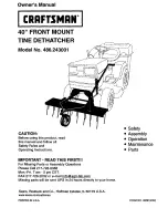
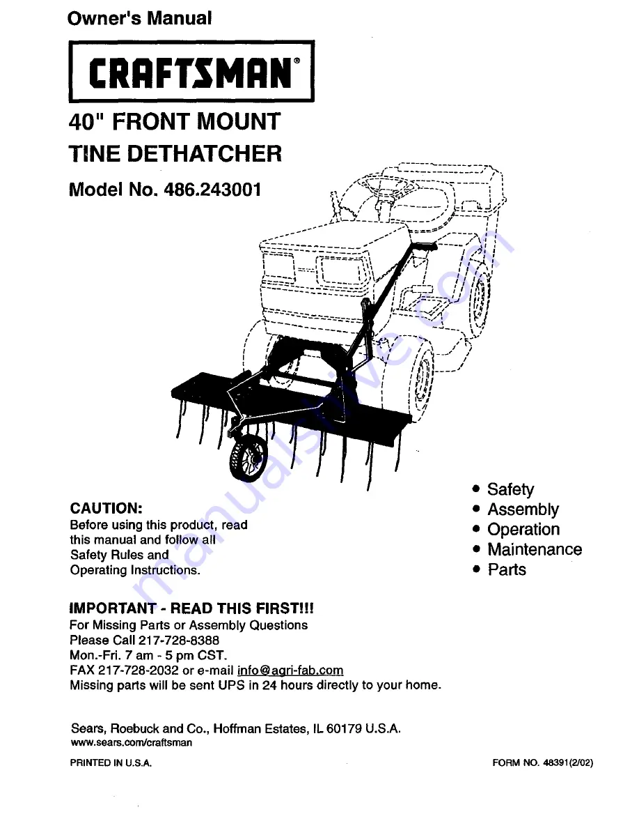
background image

Summary of Contents for 486.243001

Page 1: ... Assembly Operation Maintenance Parts IMPORTANT READ THIS FIRST H For Missing Parts or Assembly Questions Please Call 217 728 8388 Mon Fri 7 am 5 pm CST FAX 217 728 2032 or e mail info aari fab com Missing parts will be sent UPS in 24 hours directly to your home Seam Roebuck and Co Hoffman Estates IL 60179 U S A www sears com craftsman PRINTED IN U S A FORM NO 48391 2 02 ...

Page 2: ...user does not understand how to operate the equipment Exercise caution at all times when using power equipment Read safety rules in the vehicle owners manual and know how to operate your equipment before using the tine dethatcher Never operate vehicle and tine dethatcher attachment without wearing substantial footwear and do not allow anyone to ride or sit on the tine dethatcher Never allow childr...

Page 3: ...e Bolt 5 16 18 x 1 Lg Hex Bolt 5 16 18 x 1 Lg Hex Bolt 3 8 16 x 1 Lg Flat Washer 5 8 SAE Lock Washer 5 16 Lock Washer 3 8 Key Qty G 14 H 4 I 1 J 6 K 1 L 2 M 1 Description Hex Nut 5 16 18 Thd Hex Nut 3 8 16 Thd Clevis Pin 3 8 x 3 4 Hairpin Cotter 1 8 large Hairpin Cotter 3 32 small Keeper Plate Handle Grip ...

Page 4: ...l before attempting to install dethatcher hitch brackets TOOLS REQUIRED FOR ASSEMBLY 2 1 2 Wrenches 2 9 16 Wrenches REMOVAL OF PARTS FROM CARTON Remove all parts and hardware packages from the carton Lay out all parts and hardware and identify using the illustrations on pages 3 and 4 REMOVAL OF PARTS FROM TRACTOR Remove any front mounted attachments which may be installed on your tractor Mark all ...

Page 5: ... 8 lock washers and 3 8 hex nuts Place axle bushing between front ends of mounting arms centering bushing up and down Tighten bolts securely in front ends of mounting arms See figure 3 5 16 LOCK WASHER 5 16 x 1 CARRIAGE BOLT MOUNTING ARM 5 16 AXLE BUSHING HEX NUT 3 8 HEX 3 8 x 1 NUT HEX BOLT 3 8 LOCK WASHER Assemble angle mounting brackets to tine shield using four 5 16 x t carriage bolts 5 16 loc...

Page 6: ...wo self threading bolts from front cross member of tractor Assemble bolts through lower slots in hitch bracket then reinstall them back into front cmssmembar Make sure notches at top of hitch bracket and cressmember are aligned See figure 7 From behind tractor s front crossmember insert two 3 8 x 1 hex bolts through holes in crossmember shown in figure 7 and through upper slots in hitch bracket Se...

Page 7: ...le arm and handle lock bracket See figure 12 Assemble lift handle to lift handle bracket using 3 8 x 314 clevis pin and 3 32 small hairpin cotter See figure 12 LIFT HANDLE Z LIIJ SRACKE _ _ _l_ _ __ LIFT HANDLE BRACKET FIGURE 12 Raise and lock dethatcher in transport position see operation instructions on page 8 Move tractor with front mounted dethatcher onto a level surface such as a drive or gar...

Page 8: ... stud to pass through lock bracket See figure 14 NOTCH FIGURE 14 OPERATING TIPS De thatching is recommended for eady spring late fall and prior to fertilizing It is not recommended to de thatch with every mowing of the lawn The tine dethatcher can be easily removed for storage Maintenance Storage Always being with transmission in first low gear and gradually increase speed as conditions permit The...

Page 9: ...I OIL FIGURE 15 LIFT HANDLE a_ J Z _JJ cK r A FIGURE 16 STORAGE Alwaysstorein a dryarea and coatspringtineswith lightoil whennotin use TO REMOVE DETHATCHER FROM TRACTOR Refer to figure 16 Lower dethatcher to ground Remove 3 32 small hairpin cotter and 3 8 x 3 4 clevis pin from lift handle Remove handle from handle lift bracket Slide lift handle out between lift handle arm and handle lock bracket R...

Page 10: ...s on top of dethatcher shield to lock adjustment See figure 18 If you need more adjustment try moving the axle bushing up o down between the mounting arms Be sure to retighten the bolts securing the bushing See figure 18 MOUNTING ARMS AXLE BUSHING ANGLE BRACKETS GROUND To replace a spring tine a Insert a screw driver or punch into hole and pry locking tab out from center loop of spring tine b Remo...

Page 11: ... 44213 1 Wheel 44148 1 Pivot Axle 23668 1 Bushing 62600 1 Lift Handle 23675 1 Hitch Bracket Purchase Common REF PART NO NO QTY DESCRIPTION 15 43086 14 16 43083 14 17 23676 2 18 43343 6 19 _19212113 4 20 43943 1 21 44044 1 22 43055 1 23 43001 4 24 43003 4 25 43015 4 26 43063 2 27 44326 12 48391 1 Lock Washer 5 16 Hex Nut 5 16 18 Keeper Plate Hairpin Cotter 1 8 Flat Washer 5 8 Plastic Grip Clevis Pi...

Page 12: ...sears com For the replacement parts accessories and owner s manuals that you need to do it yourself call Sears PartsDirect sM 1 800 366 PART 6 a m 11 p m CST 1 800 366 7278 7 days a week www sears com partsdirect To purchase or inquire about a Sears Service Agreement 1 800 827 6655 7 a m 5 p m CST Mon Sat Para pedir servicio de reparaci6n a domicilio Au Canada pour service en fran ais 1 877 LE FOY...

Reviews: