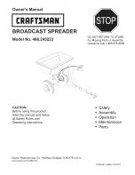
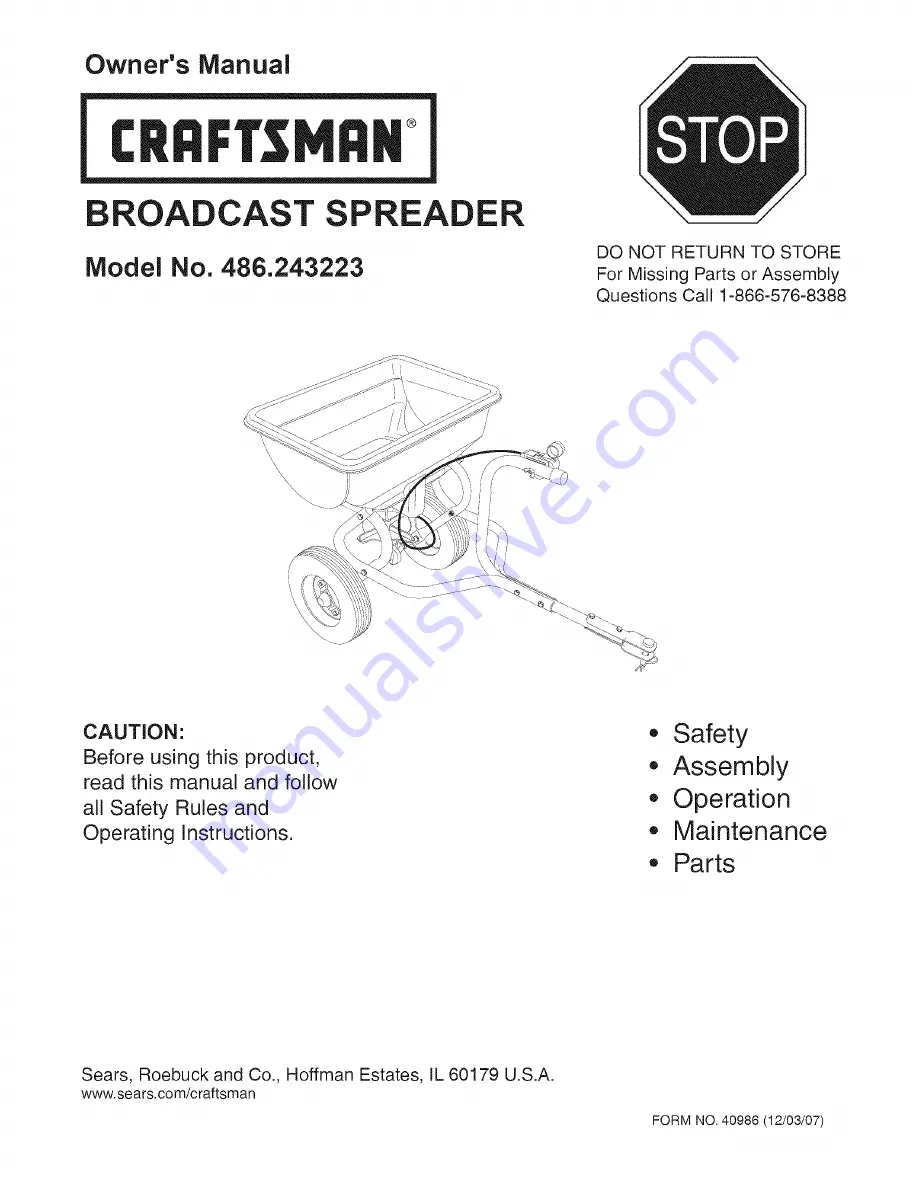
Craftsman 486.243223, Owner'S Manual
The Craftsman 486.243223 Owner's Manual is the essential guide for proper usage and maintenance of this high-quality product. With just a few clicks, you can easily download the manual for free from our website, ensuring you have all the information you need to make the most of your Craftsman 486.243223.
Share
Download


Reviews:
No comments
Related manuals for 486.243223
2112
Brand: H&S Pages: 30
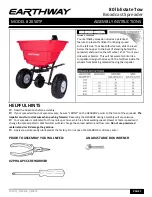
3100
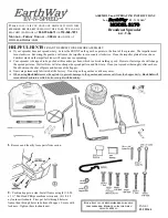
Brand: EarthWay Pages: 2
2050
Brand: EarthWay Pages: 2

2050
Brand: EarthWay Pages: 3
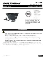
M20
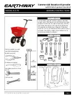
Brand: EarthWay Pages: 6
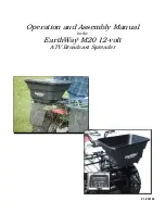
M20
Brand: EarthWay Pages: 6
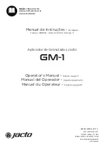
GM-1
Brand: Jacto Pages: 25
2170
Brand: EarthWay Pages: 8
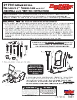
2170
Brand: EarthWay Pages: 12

3243
Brand: H&S Pages: 36
2170
Brand: EarthWay Pages: 6
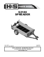
S2180
Brand: H&S Pages: 38
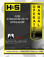
2280
Brand: H&S Pages: 34
425
Brand: Gardena Pages: 4

M30
Brand: EarthWay Pages: 6

M80
Brand: EarthWay Pages: 6
2750
Brand: EarthWay Pages: 2
2050TP
Brand: EarthWay Pages: 6


