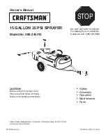
background image

7

OPERATION

KNOW YOUR  SPRAYER

Read this owner's manual and safety rules before operating your sprayer.

Compare the illustration below with your sprayer to familiarize yourself with the various controls and their locations.

FIGURE 12

BOOM ARM

  Swivels up and down and adjusts in and out 

to obtain proper nozzle positioning.

SPRAY GUN

  Unhooks from tank for spraying shrubs, 

small trees or areas inaccessible to the towed sprayer.

ON-OFF VALVE

  Turns the flow on or off from the pump to 

the boom nozzles.

ON-OFF SWITCH

  Turns pump/motor on or off.

BEFORE STARTING
It is important 

to test the boom and spray gun with plain 

water before attempting actual spraying. This will enable 

you to check the sprayer for leaks and to set the spray 

pattern and nozzle pressure. If a leak should occur, thread 
tape may be used to better seal the fitting.

PUMP PRESSURE SWITCH

The pump is equipped with a pressure switch. The 

pressure switch senses outlet pressure of the pump 
and will turn off the electrical power to the pump at a 

predetermined high pressure point (35 PSI). If the flow 
demand is very low,  the pump may reach this high 
pressure point and the switch will cause "cycling" (the 
pump cycles on and off rapidly). This is not a problem 
unless the pump is subject to continuous cycling within 
one second intervals for long periods of time.

ON-OFF ADJUSTMENT OF BOOM NOZZLES

The sprayer is equipped with an "On-Off" valve for the 
boom which allows the flow to the boom nozzles to be 

shut off.

ADJUSTING SPRAY GUN NOZZLE

Turn the nozzle on the spray gun to adjust the spray from 
a cone shaped fine mist to a straight stream. Maximum 
gun pressure is attained with the ON-OFF valve shut off.

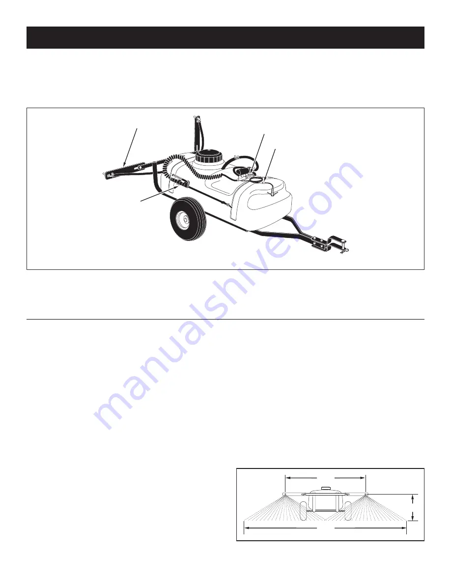
SETTING THE BOOM FOR SPRAYING

The correct positioning of the boom places the nozzles 
approximately 40" apart and 14" above the ground. This 
gives a spray width of approximately 80" with a slight 
center overlap. See figure 12.


a.  Slide the boom bars out to the ends of the slots. 


b.  Swivel the boom bars until the nozzles are


approximately 14" above the ground. 


c.  Make sure the nozzles are adjusted so that the    


openings point straight down. 

80"

40"

14"

ON-OFF SWITCH

ON-OFF VALVE

SPRAY GUN 

BOOM ARM 

Summary of Contents for 486.245315

Page 1: ...d follow all Safety Rules and Operating Instructions Safety Assembly Operation Maintenance Parts PRINTED IN U S A FORM NO 41612 01 16 15 STOP DO NOT RETURN TO STORE For Missing Parts or Assembly Questions Call 1 866 576 8388 Sears Brands Management Corporation Hoffman Estates IL 60179 U S A www sears com craftsman ...

Page 2: ...pets Read the chemical label carefully for instructions and caution notes on handling and mixing of chemicals Wear eye and hand protection and wear protective clothing when handling and applying lawn chemicals Do not spray on windy days Attachment of this sprayer may affect your tractor s braking and stability Be aware of your tractor s capabilities Refer to the safety rules in the vehicle owner s...

Page 3: ...ck KEY PART NO QTY DESCRIPTION K 736 0722 2 Lock Washer 10 L 43343 1 Hair Cotter Pin M 47623 1 Hitch Pin N 44166 2 Palnut O 712 0421 2 Knob P 45180 1 Spray Gun Clip Small Q 47397 1 Spray Gun Clip Large R 46578 2 Spacer Long S 42767 1 Coiled Hose Clamp T 27231 2 Spacer Short 1 Boom Mount Bracket 2 Lid 3 Tank with Frame Tubes 4 Spray Gun Assembly 5 Boom Assembly 6 Hitch Arms 2 7 Hitch Brackets 2 8 A...

Page 4: ... of the axle Repeat on other end of axle 1 2 FLAT WASHER LONG SPACER AXLE PALNUT SHORT SPACER Attach mounting plates to frame tubes using four 5 16 x 1 3 4 hex bolts 3 8 washers thick washers placed between the mounting plates and frame tubes 3 8 washers and 5 16 nylock nuts Tighten the bolts FIGURE 1 3 8 WASHER 3 8 WASHER 5 16 x 1 3 4 HEX BOLT THICK WASHER 5 16 NYLOCK NUT FIGURE 3 Assemble a hitc...

Page 5: ... nylock nuts Position each bolt behind one of the cross bolts in the hitch arms Do not tighten yet At this time tighten all bolts starting with the bolts in figure 3 then the bolts in figure 4 5 16 NYLOCK NUT BOOM MOUNT BRACKET 5 16 x 2 HEX BOLT Assemble boom mount bracket to rear of hitch tubes using two 5 16 x 2 hex bolts and 5 16 nylock nuts 5 16 x 2 HEX BOLT 5 16 NYLOCK NUT 5 16 x 1 1 4 HEX BO...

Page 6: ...gun into the clips on the side of the tank FIGURE 11 FIGURE 9 VIEWED FROM FRONT DANGER Never allow negative pin on plug to come in contact with positive hot post on battery Fire or explosion may result FIGURE 10 IMPORTANT Connect sprayer to 12 volt batteries only To connect wire harness to tractor attach the red wire to positive post on battery or to HOT connection on a tractor switch or ammeter B...

Page 7: ...electrical power to the pump at a predetermined high pressure point 35 PSI If the flow demand is very low the pump may reach this high pressure point and the switch will cause cycling the pump cycles on and off rapidly This is not a problem unless the pump is subject to continuous cycling within one second intervals for long periods of time ON OFF ADJUSTMENT OF BOOM NOZZLES The sprayer is equipped...

Page 8: ...R V antifreeze through the entire plumbing Proper care and maintenance will prolong the life of the sprayer Before each use After each use Every season Before storage MAINTENANCE STORAGE Service Dates MAINTENANCE SCHEDULE Fill in dates as you complete regular service CUSTOMER RESPONSIBILITIES Read and follow the maintenance schedule and the maintenance procedures listed in this section Check for l...

Page 9: ...75 1 36 201 0 100 5 67 8 50 5 40 5 26 8 20 0 IMPERIAL GALLONS Liters PER 1000 SQ FT BASED ON WATER 3 80 25 30 1 0 0 50 0 34 0 26 0 20 0 14 0 10 2032 mm 1 75 1 36 4 54 2 27 1 55 1 18 0 91 0 64 0 54 3 80 25 36 53 26 5 17 7 13 3 10 6 7 1 5 3 Tip Spray Pressure Tip Capacity GALLONS PER 1000 SQ FT BASED ON WATER No Width PSI U S Gallons Inches Per Minute 1 MPH 2 MPH 3 MPH 4 MPH 5 MPH 7 5 MPH 10 MPH 3 8...

Page 10: ... 9 10 37 44 27 43 36 42 39 41 40 57 12 27 38 27 36 43 42 27 39 41 40 12 27 16 11 46 D 5 19 7 35 1 B B C A C 3 6 6 27 27 21 8 20 23 23 24 28 26 13 32 27 27 27 27 52 56 54 56 54 53 31 44 15 49 47 33 29 30 31 48 60 59 14 D 15 15 44 15 34 51 50 50 57 45 18 18 18 18 15 29 55 58 22 ...

Page 11: ...Gun 26 47416 1 Valve Nylon 1 4 27 41486 11 Clamp 3 8 Schedule E 28 47415 1 Tee Nylon 1 4 NPT 29 48296 2 Frame Tube 30 24860 2 Hitch Arm 31 23014 2 Hitch Bracket REF NO PART NO QTY DESCRIPTION 32 42767 1 Clamp Coiled Hose 33 24584 1 Axle 1 2 34 46503 2 Wheel 35 46700 1 Lid 36 24122 2 Boom Bar 37 24585 1 Bracket Boom Mount 38 47394 1 Tee Plastic 3 8 Hose 39 45028 2 Nozzle SS Floodjet 40 45029 2 Stra...

Page 12: ...stas a preguntas o problemas y ordenar piezas o pedir servicio para la reparación de su equipo To help us help you register your product at www craftsman com registration Para poderte ayudar mejor registra tu producto en www craftsman com registration Join the Craftsman Club today Receive exclusive member benefits including special pricing and offers project sharing expert advice and SHOP YOUR WAY...

Reviews: