background image

12

CHECK FOR LOOSE FASTENERS


Before each use make a thorough visual check of 
the spreader for any bolts and nuts which may have 
loosened. Retighten any loose bolts and nuts.

CHECK FOR WORN OF DAMAGED PARTS

•  Check for worn or damaged parts before each use. 

Repair or replace parts if necessary.

CHECK TIRE INFLATION

•  Check if tires are adequately inflated before each 

use. Do not inflate beyond maximum recommended 
pressure.

Service Dates

Bef

ore each use

After each use

Ev

ery season

Bef

ore stor

age

As instr

ucted

  MAINTENANCE SCHEDULE
 

Fill in dates as you

  complete regular service.
  Check for loose fasteners 


  Check for worn or damaged parts   


X

  Check tire inflation 


X

  Cleaning 


X

  Lubricate 


CUSTOMER RESPONSIBILITIES

•  Read and follow the maintenance schedule and the maintenance procedures listed in this section. 

MAINTENANCE/STORAGE

FIGURE 18

STORAGE

•  Rinse inside of hopper and exterior of spreader and 

dry off before storing.

•  Store in a clean, dry area.


CAUTION:  DO NOT 

inflate tires beyond 

the maximum recommended pressure 
printed on side of tire.

CLEANING

•  Rinse inside of hopper and exterior of spreader and 

dry off before storing.

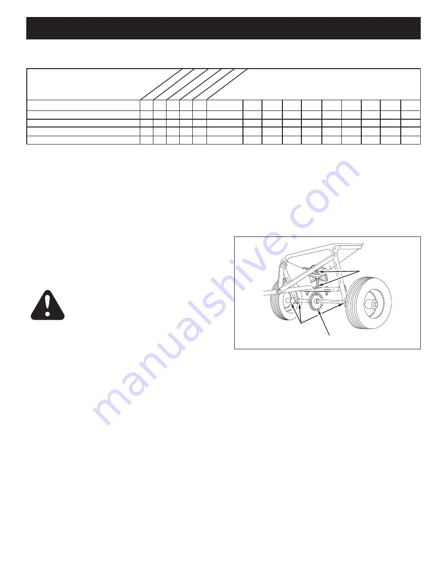
LUBRICATE 

(See figure 18.)

•  Lightly apply automotive grease as needed to the 

sprocket and gear.

•  Oil the nylon bushings on the vertical sprocket shaft 

and on the axle at least once a year, or more often as 
needed.

•  Oil right hand (idler) wheel bearing at least once a 

year or more often as needed.

GREASE

OIL

OIL

Summary of Contents for 486.245951

Page 1: ...ED IN U S A FORM NO 49914 REV 05 09 08 Sears Roebuck and Co Hoffman Estates IL 60179 U S A www sears com craftsman CAUTION Before using this product read this manual and follow all Safety Rules and Operating Instructions STOP DO NOT RETURN TO STORE For Missing Parts or Assembly Questions Call 1 866 576 8388 ...

Page 2: ...l number and the date of purchase and keep in a safe place for future reference WARRANTY ONE YEAR FULL WARRANTY When operated and maintained according to the instructions supplied with it if this Spreader fails due to a defect in material or workmanship within one year from the date of purchase call 1 800 4 MY HOME to arrange for free repair or replacement if repair proves impossible If this produ...

Page 3: ...chemicals Never operate tractor and spreader attachment without wearing substantial footwear and do not allow anyone to ride or sit on spreader attachment frame Never allow children to operate the tractor or spreader attachment and do not allow adults to operate without proper instructions Always begin with the transmission in first low gear and with the engine at low speed and gradually increase ...

Page 4: ...P 2 Spacers Q 1 Nylon Wing Nut R 1 Adjustable Stop S 1 Vinyl Cap T 1 Grip U 1 Flow Control Link V 1 Drive Pin KEY QTY DESCRIPTION A 4 Hex Bolt 5 16 x 1 3 4 B 6 Hex Bolt 1 4 x 1 3 4 C 2 Hex Bolt 3 8 x 3 4 D 2 Hex Bolt 1 4 x 1 E 1 Carriage Bolt 1 4 x 3 4 F 8 Nylock Hex Nut 1 4 G 4 Nylock Hex Nut 5 16 H 2 Nylock Hex Nut 3 8 I 4 Nylon Washer J 7 Flat Washer 5 16 K 4 Flat Washers 3 4 KEY QTY DESCRIPTIO...

Page 5: ...7 9 10 7 Hitch Bracket 8 Hitch Tube 9 Flow Control Mount Bracket 10 Flow Control Arm 11 Hopper Cover 12 Screen Hardware Package see page 4 TOOLS REQUIRED FOR ASSEMBLY 1 Pliers 2 7 16 Wrenches 2 1 2 Wrenches 2 9 16 Wrenches REMOVAL OF PARTS FROM CARTON Remove all parts and hardware packages from the carton Lay out all parts and hardware and identify using the illustrations on pages 4 and 5 ...

Page 6: ...A FLAT WASHER 1 8 x 1 1 2 COTTER PIN AIR VALVE FIGURE 4 Assemble a spacer a 3 4 flat washer a wheel air valve facing out and another 3 4 flat washer onto the end of the axle that has both the large and small holes See figure 4 Install a 1 8 x 3 4 cotter pin into the small hole in the end of the axle See figure 4 Open the bail on the drive pin and install it through the wheel and the large hole in ...

Page 7: ... HEX NUT VINYL CAP FLOW CONTROL MOUNTING TUBE FIGURE 8 Assemble the vinyl grip onto the flow control arm See figure 8 Insert the flow control arm down through the slot in the flow control bracket Assemble the small hole of the flow control link to the flow control arm using a 1 4 x 1 hex bolt a nylon washer and a 1 4 nylock hex nut as shown in figure 8 Tighten carefully The flow control link shoul...

Page 8: ...table stop into the ON end of the slot in the top of the flow control mounting bracket Secure with the 1 4 x 3 4 carriage bolt a nylon washer a 5 16 flat washer and the nylon wing nut See figure 12 FIGURE 12 FIGURE 11 NYLON WING NUT OFF ON 1 2 3 4 6 7 8 9 10 5 5 16 FLAT WASHER NYLON WASHER ADJUSTABLE STOP 1 4 x 3 4 CARRIAGE BOLT 5 16 FLAT WASHER 3 32 HAIR COTTER PIN FLOW CONTROL ROD OFF ON 1 2 3 4...

Page 9: ...re 16 Tighten the bolts and nuts when finished FIGURE 16 Assemble the hitch bracket to the hitch extension bracket using two 3 8 x 3 4 hex bolts inserted from the bottom and two 3 8 nylock hex nuts See figure 15 Assemble the hitch pin through the hitch bracket and the hitch extension bracket and secure with the hair cotter pin See figure 15 1 4 NYLOCK HEX NUT 1 4 x 1 3 4 HEX BOLT 3 8 x 3 4 HEX BOL...

Page 10: ...le stop to the desired flow rate setting and retighten the wing nut The higher the setting number the wider the opening in the bottom of the hopper Refer to the application chart on page 11 and to the instructions on the fertilizer bag to select the proper flow rate setting Pull the flow control arm against the adjustable stop for the on position and toward the hopper for the off position FLOW CON...

Page 11: ...e closure plate before turning or stopping the vehicle If fertilizer is accidentally deposited too heavily in a small area soak the area thoroughly with a garden hose or sprinkler to prevent burning of the lawn To insure uniform coverage make each pass so that the broadcast pattern slightly overlaps the pattern from the previous pass as shown in figure 17 The approximate broadcast widths for diffe...

Page 12: ...rn or damaged parts X X Check tire inflation X Cleaning X X Lubricate X X CUSTOMER RESPONSIBILITIES Read and follow the maintenance schedule and the maintenance procedures listed in this section MAINTENANCE STORAGE FIGURE 18 STORAGE Rinse inside of hopper and exterior of spreader and dry off before storing Store in a clean dry area CAUTION DO NOT inflate tires beyond the maximum recommended pressu...

Page 13: ...d for minimum backlash Add grease to gear and sprocket REPLACING AGITATOR If the agitator hairpin becomes damaged or worn it can be replaced See figure 19 SPROCKET SHAFT AGITATOR HAIRPIN SHAFT SUPPORT PLATE SLOTTED GEAR LOCKED UP SPREADER Turn the spreader over so that the wheels are off the ground Loosen all three nuts on the shaft support plate just enough so that the bolts can be turned easily ...

Page 14: ...3 59 27 26 28 3 19 36 9 9 46 9 57 9 40 14 17 37 37 24 50 13 9 65 29 5 4 9 35 35 E 6 52 32 7 C 29 40 53 25 E 1 39 10 31 2 39 40 58 55 56 58 49 40 B 61 9 B D 16 63 42 44 8 37 9 7 48 A 13 41 60 47 62 7 45 58 39 39 39 54 9 54 49 50 11 51 64 54 15 9 A 13 11 54 54 34 OF F ON 1 2 3 4 6 7 8 9 10 5 35 38 30 ...

Page 15: ...1 Hairpin Agitator 32 43070 5 Washer Flat 3 8 33 43054 2 Bolt Hex 3 8 16 x 2 Lg 34 48586 1 Rod Flow Control REF PART QTY DESCRIPTION NO NO 35 23525 4 Brace Hitch 36 23762 1 Shaft Support Plate 37 1509 69 6 Bolt Hex 1 4 20 x 1 3 4 38 47441 1 Screen 39 1543 69 12 Washer Nylon 40 43088 15 Washer Flat 1 4 Std 41 24858 1 Stop Adjustable 42 24915 1 Bracket Flow Control Mount 43 62474 1 Gear Assembly 44 ...

Page 16: ...iances and items like garage door openers and water heaters 1 800 4 MY HOME 1 800 469 4663 Call anytime day or night U S A and Canada www sears com www sears ca For expert home solutions advice www managemyhome com Our Home For repair of carry in items like vacuums lawn equipment and electronics call or go on line for the location of your nearest Sears Parts Repair Service Center 1 800 488 1222 U ...

Reviews: