background image

18

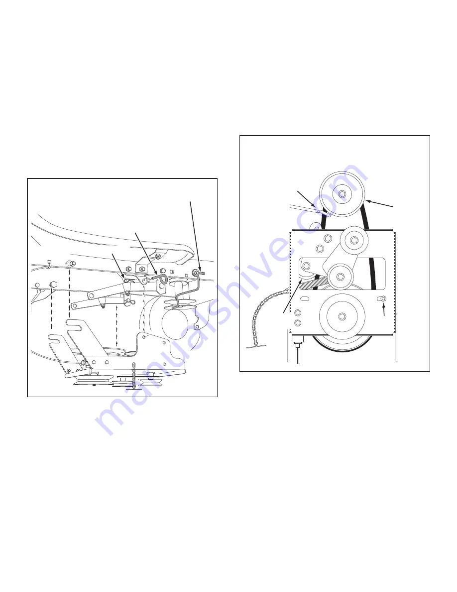
FIGURE 40 

VIEWED FROM UNDERNEATH

FIGURE 39

STEP 40:  (SEE FIGURE 40)

•  Assemble the short "V" belt onto the engine pulley 

and then onto the large pulley on top of the clutch/idler 
assembly. The belt must be placed to the inside of the 
engine pulley keeper, the idler pulley and the keeper 
bolt located beside the large pulley.

IMPORTANT:


Do Not

 assemble the "V" belt around the 

outside of the engine pulley keeper or the keeper bolt. 

• 

Go to step 48 on page 21.

STEP 39:  (SEE FIGURE 39)

•  Remove the engine pulley keeper from the side of 

the tractor frame by removing the washer and nut 

that secure the keeper. Attach the new pulley keeper 
supplied with the snow thrower, reusing the original 
bolt, washer and nut.

 
NOTE:

 Some tractors may already be equipped with a

pulley keeper that is identical to the new one supplied.

•  Attach the clutch/idler assembly to the tractor frame 

as follows. Hook the assembly's notched arms onto 

the two shoulder bolts you assembled to the inside 
of the tractor frame. Lift the front of the assembly and 
attach it to the R.H. and L.H. hanger brackets using 

two pivot lock pins (MM) and 1/8" hairpin cotters (KK).

NEW ENGINE PULLEY KEEPER WITH
ORIGINAL BOLT, NUT AND WASHER

PIVOT LOCK PIN (MM)
(use second hole)

1/8" HAIRPIN COTTER (KK)

ENGINE 
PULLEY 

KEEPER BOLT 

IDLER 
PULLEY 

ENGINE 
PULLEY 
KEEPER 

Left Side 
of Tractor 

CLUTCH/IDLER ASSEMBLY

Summary of Contents for 486.248381

Page 1: ...7 08 Sears Roebuck and Co Hoffman Estates IL 60179 U S A www sears com craftsman CAUTION Before using this product read this manual and follow all Safety Rules and Operating Instructions Safety Assembly Operation Maintenance Parts STOP DO NOT RETURN TO STORE For Missing Parts or Assembly Questions Call 1 866 576 8388 ...

Page 2: ...g to the instructions supplied with it if this Snowthrower fails due to a defect in material or workmanship within one year from the date of purchase call 1 800 4 MY HOME to arrange for free repair or replacement if repair proves impossible If this product is used for commercial or rental purposes this warranty applies for only 90 days from the date of purchase This warranty gives you specific leg...

Page 3: ...arts to vibrate abnormally stop the engine immediately and check for the cause Vibration is generally a warning of trouble Stop the engine whenever you leave the operating position before unclogging the snow thrower or making any adjustments or inspections Take all possible precautions when leaving the unit unattended Disengage the attachment clutch lever or switch lower the snow thrower shift int...

Page 4: ...4 G A D F K L M N O S H I BB Y C CC E AA P U W X V DD QQ KK R EE FF II HH GG NOT SHOWN ACTUAL SIZE SHOWN ACTUAL SIZE JJ J Q PP LL MM OO Z T NN B RR TT SS HARDWARE PACKAGE CONTENTS ...

Page 5: ...tor RR 1 Small Spacer SS 1 Large Spacer TT 1 Pulley A 1 Hex Bolt 1 2 x 1 1 4 B 1 Hex Bolt 3 8 x 3 1 4 C 2 Hex Bolt 3 8 x 1 D 2 Hex Bolt 5 16 x 1 3 4 E 4 Hex Bolt 5 16 x 3 4 F 6 Hex Bolt 1 4 x 1 G 6 Hex Bolt 3 8 x 1 Thread Forming H 2 Hex Bolt 3 8 x 3 4 Thread Forming I 2 Hex Bolt 5 16 x 3 4 Thread Forming J 2 Slotted Truss Head Bolt 3 8 x 1 K 6 Carriage Bolt 3 8 x 1 L 2 Carriage Bolt 5 16 x 1 3 4 ...

Page 6: ...Cable 12 Cable Bracket 13 Plastic Keg 14 L H Hanger Bracket Outside Mounting 15 R H Hanger Bracket Outside Mounting 16 Clutch Idler Assembly 17 V Belt Drive Short 46989 18 V Belt Drive Long 48138 19 V Belt Auger Attached to Housing Assembly 20 Chute and Control Cable Assembly 21 Housing Assembly 22 Weight Tray 23 L H Hanger Bracket Inside Mounting 24 R H Hanger Bracket Inside Mounting Hardware Pac...

Page 7: ...al instructions Mark all loose parts and save for reassembly Remove the tractor hood Refer to your tractor owner s manual for removal instructions CAUTION Beforestartingtoassemblethe snow thrower remove the spark plug wire s set the parking brake and remove the key from the tractor ignition FIGURE 2 RIGHT SIDE VIEW IMPORTANT Right hand R H and left hand L H side of the tractor are determined from ...

Page 8: ...ff the bolt that goes through the plate INSTALL HANGER BRACKETS AND SHOULDER BOLTS TO OUTSIDE OF FRAME STEP 5 SEE FIGURE 5 Remove the bolt if present in the hole directly behind the brake rod on the left side of the tractor frame Attach the L H Hanger Bracket tube facing out to the hole using a 5 16 x 3 4 self threading bolt I Install a round head shoulder bolt Q into the hole that is 9 1 2 to the...

Page 9: ...tractor Using the wrong length belt may cause premature bearing or belt failure STEP 10 SEE FIGURE 10 Two different length drive belts are included with your snow thrower Tractors with manual attachment clutches and single front deck suspension brackets use the 56 drive belt with 48138 printed on the outside of the belt DO NOT USE the other belt Slightly loosen the hex bolt next to the flat idler ...

Page 10: ...per bolt next to the large pulley Go to step 48 on page 21 FIGURE 13 VIEWED FROM UNDERNEATH ENGINE PULLEY ENGINE PULLEY Left Side of Tractor ENGINE PULLEY KEEPER ENGINE PULLEY KEEPER KEEPER BOLT IDLER PULLEY FIGURE 11 5 64 HAIR COTTER PIN SPACER 1 4 WASHER TRACTOR S CLUTCH CABLE CABLE BRACKET GROOVE 5 64 HAIR COTTER PIN JJ 1 4 WASHER T SPACER RR TRACTOR S CLUTCH CABLE CABLE BRACKET 5 64 HAIR COTTE...

Page 11: ...eely Attach a 3 32 hairpin cotter LL to the chain placing it in the fifth link from the spring CHAIN L H SIDE 3 32 HAIR COTTER PIN LL 5TH LINK LEFT SIDE 3 8 HEX LOCK NUT DD SPRING RIGHT SIDE ATTACH SPRING HERE STEP 15 SEE FIGURE 15 Turn the clutch idler assembly upside down and place the extra tensioning chain PP through the left front hole FIGURE 15 TENSIONING CHAIN PP LEFT FRONT HOLE STEP 17 SEE...

Page 12: ...as the 3 32 hairpin cotter in the chain will allow Secure the chain in this position by inserting a 1 8 hairpin cotter KK through the chain IMPORTANT Do Not assemble the drive belt around the outside of the keeper bolt beside the large pulley Go to step 48 on page 21 FIGURE 19 VIEWED FROM UNDERNEATH 1 8 HAIRPIN COTTER KK ENGINE PULLEY ENGINE PULLEY KEEPER BOLT IDLER PULLEY CHAIN PP L H SIDE FIGURE...

Page 13: ...rame Use three 3 8 x 1 thread forming bolts G 1 2 washers V and 3 8 lock washers S Tighten all bolts and repeat for the L H side NOTE If the bolt inserts freely into the front hole assemble a 3 8 flanged nut BB onto the bolt 3 3 8 x 1 THREAD FORMING BOLTS G 3 3 8 LOCK WASHERS S 3 8 FLANGED NUT BB SEE NOTE 3 1 2 WASHERS V FIGURE 23 RIGHT SIDE VIEW STEP 21 SEE FIGURE 20 Remove bolts from front three...

Page 14: ...a 3 8 x 1 carriage bolt K and a 3 8 flanged nut BB Bolt head goes on inside of tractor frame Repeat for the R H side STEP 28 SEE FIGURE 28 Assemble a shoulder bolt P and 3 8 flanged nut BB to the R H side of the tractor frame using the first empty hole to the rear of the R H hanger bracket Bolt goes on inside of frame FIGURE 27 LEFT SIDE VIEW INSTALLING SHOULDER BOLTS STEP 27 SEE FIGURE 27 Remove ...

Page 15: ...RM SUSPENSION ARM TRUNNION II REMOVE EXTENSION BOLT AND NUT IF PRESENT STEP 30 SEE FIGURE 30 Attach the two suspension arms to the inside of the clutch idler assembly using two 5 16 x 3 4 hex bolts E 5 16 washers U and 5 16 nylock nuts CC for each arm Place the washers between the arms and the assembly frame Insert a tensioning chain through the hole shown and attach the end link to the spring on ...

Page 16: ...BOLT 3 8 THIN WASHER W NEW ENGINE PULLEY KEEPER WITH ORIGINAL BOLT NUT AND WASHER STEP 34 SEE FIGURE 34 Assemble the short V belt onto the engine pulley and then onto the large pulley on top of the clutch idler assembly The belt must be placed to the inside of the engine pulley keeper the idler pulley and the keeper bolt located beside the large pulley IMPORTANT Do Not assemble the V belt around t...

Page 17: ...OTTER PIN JJ STEP 35 SEE FIGURE 35 Attach the two suspension arms to the inside of the clutch idler assembly using two 5 16 x 3 4 hex bolts E 5 16 washers U and 5 16 nylock nuts CC for each arm Place the washers between the arms and the assembly frame Insert a tensioning chain through the hole shown and attach the end link to the spring on the lower idler arm FIGURE 35 5 16 x 3 4 HEX BOLT E 5 16 N...

Page 18: ... nut that secure the keeper Attach the new pulley keeper supplied with the snow thrower reusing the original bolt washer and nut NOTE Some tractors may already be equipped with a pulley keeper that is identical to the new one supplied Attach the clutch idler assembly to the tractor frame as follows Hook the assembly s notched arms onto the two shoulder bolts you assembled to the inside of the trac...

Page 19: ... table below to select the correct drive belt for your type tractor The part number is printed on the outside of the belt Set aside the belt that is not for your tractor to avoid accidentally using it 55 BELT PART 46989 TRACTOR TYPE DECK SIZE CLUTCH TYPE 56 BELT PART 48138 TRACTOR TYPE DECK SIZE CLUTCH TYPE LT Lawn Tractor 48 Electric LT Lawn Tractor 38 42 46 Electric TABLE 2 STEP 41 SEE FIGURE 41...

Page 20: ...s Hook the assembly s notched arms onto the two shoulder bolts you assembled to the inside of the tractor frame Lift the front of the assembly and attach it to the R H and L H hanger brackets using two pivot lock pins MM and 1 8 hairpin cotters KK FIGURE 45 RIGHT SIDE VIEW PIVOT LOCK PIN MM use second hole 1 8 HAIRPIN COTTER KK CLUTCH IDLER ASSEMBLY HEX BOLTS DRIVE BELT FLAT IDLER PULLEY FIGURE 44...

Page 21: ...he lift release cable tilt the snow thrower forward onto the spiral auger FIGURE 47 RIGHT SIDE VIEW 5 16 NYLOCK NUT CC 5 16 x 1 3 4 HEX BOLT D ASSEMBLY OF THE SNOW THROWER STEP 50 SEE FIGURE 49 Tilt the snow thrower back down to the ground Remove the nylon tie which fastens the auger drive belt to the discharge housing leaving the belt assembled around the pulleys Remove the nylon tie which fasten...

Page 22: ...he plastic chute keepers Place the plastic cap NN onto the short end of the anti rotation bracket Position the crank rod spiral see figure 51 so that it does not rub against the bottoms of the notches in the chute flange Tighten the nuts Check if the crank rod rotates the chute freely If not loosen by 1 4 turn each of the six hex bolts holding the chute keepers to the chute flange Secure the contr...

Page 23: ...llation of the attachment pin until you have assembled the belt as instructed in steps 56 and 57 ATTACHING SNOW THROWER TO TRACTOR BEFORE INSTALLING THE AUGER BELT STEP 56 SEE FIGURE 55 The auger belt comes preassembled to the pulleys on the snow thrower housing Make sure the belt passes over the top of the auger pulley and then twists 1 4 turn to pass underneath each side idler pulley The V side ...

Page 24: ... 1 2 x 1 1 4 HEX BOLT A 5 16 x 1 CARRIAGE BOLT N SIDE BRACE CROSS BRACE 3 8 x 3 4 SELF THREADING BOLT H 5 16 NYLOCK NUT CC 1 2 NYLOCK NUT EE WEIGHT TRAY WEIGHT TRAY 5 16 NYLOCK NUT CC DRAWBAR 5 16 x 1 CARRIAGE BOLT N CLUTCH IDLER ASSEMBLY ATTACHING WEIGHT TRAY TO TRACTOR ATTACHING TO LT LAWN TRACTORS WITH A SINGLE FRONT DECK SUSPENSION BRACKET STEP 60 SEE FIGURE 58 NOTE Go to step 63 on page 26 if...

Page 25: ...CE CROSS BRACE 5 16 NYLOCK NUT CC 3 8 FLANGED NUT BB 3 8 x 1 HEX BOLT C DRAWBAR WEIGHT TRAY WEIGHT TRAY 5 16 x 1 CARRIAGE BOLT N FIGURE 60 1 2 x 1 1 4 HEX BOLT A 5 16 x 1 CARRIAGE BOLT N SIDE BRACE CROSS BRACE 5 16 NYLOCK NUT CC ORIGINAL HEX BOLT or SEE NOTE 1 2 NYLOCK NUT EE WEIGHT TRAY WEIGHT TRAY 5 16 x 1 CARRIAGE BOLT N ATTACHING TO LAWN LT TRACTORS WITH DUAL FRONT DECK SUSPENSION BRACKETS STE...

Page 26: ...O REAR FENDER STEP 65 SEE FIGURE 63 If your tractor is not equipped with rear reflectors assemble the supplied rear reflectors QQ to the rear fender Place the reflectors as close to the bottom of the fender and as far apart as the shape of the fender will allow FIGURE 63 ATTACHING KEGTO WEIGHTTRAY STEP 64 SEE FIGURE 62 Place the plastic keg on the weight tray and fill with approximately 75 lbs of ...

Page 27: ...leared Refer to the Service and Adjustments section Make sure the tractor engine has the correct oil for winter operation SAE 5W 30 Refer to tractor owner s manual HOW TO START YOUR SNOW THROWER The tractor should be sitting with the engine running at full throttle Move the attachment clutch to the engaged position starting the snow thrower before the tractor clutch is engaged HOW TO STOP YOUR SNO...

Page 28: ...d For maximum snow removal and discharge maintain high engine r p m full throttle It is advisable to operate the lawn tractor at a slow ground speed 1st gear for safe and efficient snow removal In deep drifted or banked snow it will be necessary to use full throttle and a slow ground speed 1st gear Drive forward into the snow depress the tractor s clutch brake pedal and allow the spiral auger to c...

Page 29: ... to keep the housing and the scraper plate level See figure 64 LIFT RELEASE CABLE ADJUSTMENT If the lift rod does not lock the snow thrower securely in the transport position loosen the upper hex nut on the lift bracket a few turns and tighten the lower hex nut Refer to figure 48 on page 21 If the lift rod fails to unlock completely to lower the snow thrower loosen the lower hex nut on the lift br...

Page 30: ...igure 54 on page 23 Lock the snow thrower s lift handle in the down position to decrease belt tension Release the spring tension from the auger belt idler arm on the bottom of the clutch idler assembly Remove the auger drive belt from the clutch idler assembly See figure 56 on page 23 Pull the spiral auger housing assembly off of the tractor CAUSE PROBLEM CORRECTION Clogged discharge chute Spiral ...

Page 31: ...31 NOTES ...

Page 32: ...32 NOTES ...

Page 33: ...33 NOTES ...

Page 34: ...34 PARTS REPAIR PARTS FOR MODEL 486 248381 42 SNOW THROWER ...

Page 35: ...earing Split 3 4 35 24279 2 Skid Shoe 36 48015 4 Washer Nylon 37 784 5618 2 Housing Bearing 38 24393 1 Bracket Chute Crank ref part no qty description 39 24281 1 Bracket Idler 40 49933 2 Shoulder Bolt Round Head 41 65367 1 Hanger Bracket Assembly L H 42 65450 1 Hanger Bracket Assembly R H 43 41576 2 Hex Bolt 3 8 16 x 1 3 4 44 44377 1 Hex Bolt 3 8 24 x 1 45 784 5594 1 Bracket Cable 46 746 0929 1 Ca...

Page 36: ...36 REPAIR PARTS FOR MODEL 486 248381 42 SNOW THROWER 73 36 60 76 61 65 75 62 11 65 75 75 62 63 32 33 ...

Page 37: ... 47027 1 Tube Crank Rod Support 40 741 0475 2 Bushing 3 8 Plastic ref part no qty description 41 703 2735A 1 Bracket Chute Crank 42 720 0201A 1 Knob Crank 43 44917 1 Palnut 3 8 45 63579 1 Assembly Chute Crank Rod 46 784 5604A 1 Handle Chute Tilt 47 720 04039 1 Knob 48 603 0302 1 Assembly Chute Tilt Bracket 49 731 1313C 1 Guide Cable 50 746 0928 1 Cable Chute Control 51 746 0929 1 Cable Chute Contr...

Page 38: ...Bolt 5 16 18 x 1 26 46989 1 Belt V Type Drive 55 48138 1 Belt V Type Drive 56 27 47846 1 Belt V Type Auger 28 47044 1 Pulley V Type 4 29 47025 1 Hex Bolt 5 16 18 x 3 1 2 30 43432 1 Hex Bolt 3 8 16 x 2 1 2 31 43054 3 Hex Bolt 3 8 16 x 2 32 24571 1 Spacer 33 24472 1 Spacer Pivot 34 43070 8 Washer 3 8 35 46959 1 Spring 36 46963 2 Chain 37 43055 1 Pin Hair Cotter 3 32 38 23727 1 Spacer 39 43088 1 Wash...

Page 39: ... speed on slopes 1 Fold this page along dotted line indicated above 2 Hold page before you so that its left edge is vertically parallel to a tree trunk or other upright structure 3 Sight across the fold in the direction of hill slope you want to measure 4 Compare the angle of the fold with the slope of the hill ONLY RIDE UP AND DOWN HILL NOT ACROSS HILL F O L D A L O N G D O T T E D L I N E T H I ...

Page 40: ...that you need to do it yourself For Sears professional installation of home appliances and items like garage door openers and water heaters 1 800 4 MY HOME 1 800 469 4663 Call anytime day or night U S A and Canada www sears com www sears ca Our Home For repair of carry in items like vacuums lawn equipment and electronics call anytime for the location of your nearest Sears Parts Repair Service Cent...

Reviews: