background image

Summary of Contents for 536.249810

Page 1: ...s Safety Rules and Operating Instructions Manual del usario Recolector de hierba Montaje posterior para tractores de 30 con motor trasero Modelo 536 249810 PRECAUCION Antes de usar este producto lea este manual y siga todas las reglas de seguridad e instrucciones de operaci6n Seguridad Ensamblaje Operacion Mantenimiento Piezas Sears Roebuck and Co Hoffman Estates IL 60179 U S A F 020902L www sears...

Page 2: ...RASS BAGGER Record in the space below the serial number and the date of purchase of this unit The model number and serial number are found on a decal attached to the unit Model Number 536 24981 Serial Number Date of Purchase Keep these numbers for future reference Congratulations on your purchase of a Craftsman Grass Bagger It has been designed engineered and manufactured to give you the best poss...

Page 3: ...ment or repair to the machine 18 Use care when pulling loads or using heavy equipment a Use only approved drawbar hitch points b Limit loads to those you can safely control c Do not turn sharply Use care when backing d Use counterweights or wheel weights when suggested in the Instruction Book 19 Do not operate this machine if you are taking drugs or other medication which can cause drowsiness or a...

Page 4: ...y the blade attachment nuts tight Frequently check the blade s for wear or damage such as cracks and nicks A blade that is bent or damaged must be immediately replaced with an original equipment blade from an authorized service dealer For safety replace the blade every two years Keep the equipment in good condi tion 4 Never tamper with the safety devices Check their proper operation regularly 5 To...

Page 5: ...Short blade type screwdriver 1 6 Open end wrenchs 3 8 1 2 7 16 9 16 7 Socket set recommended HARDWARE PACKAGE CONTENTS The fasteners and other loose parts are shown below The fasteners are shown at full size The quantity is shown in brackets On some models all of the fasteners are not required 1 Bolt 2 Carriage Bolt 1 Carriage Bolt 17x2 2 17x104 2 Washer Washer 15x84 15x85 15x88 15x89 15x79 2 Flan...

Page 6: ...S BagCover BagPlateand HangerAssembly Connecting Tube Cloth Bag Extension J Tube BagPlate Baffle Bag Frame Tube BagFrame HitchExtension BagTop Hinge Bag LidRod j DumpLever Grip Leaf Spring J HardwarePack LiteratureKit F O20902L 6 ...

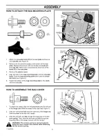
Page 7: ...ns A apart 3 Wire Frame Wire Frame Bottom A Bottom Tube Figure First put the cut out located on the right side of the grass bag around the handle support see Figure 2 4 Then slide the grass bag over the wire frame Cut Out Grass Bag Handle Support Wire Frame Figure 2 5 Attach the clips to the wire frame see Figure 3 Clips Wire Frame Figure 3 Mount the handle on the handle support and secure with bo...

Page 8: ...tom of the bag mounting plate to the studs with the knobs H Shoulder Bolts Bag Mounting Plate H Studs Figure 5 Figure 6 HOW TO ASSEMBLE THE BAG COVER L 15x84 To attach the cover slide the left pivot hole onto the left end of the hinge rod Slide the cover to the right see Figure 7 2 Slide the right pivot hole onto the right end of the hinge rod Side the cover to the left until it stops 3 Slide the ...

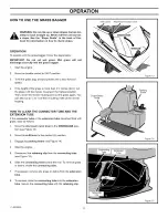
Page 9: ...Housing Extension Tube Wingnuts Figure 8 3 4 Slide the straight end of the connecting tube through the cut out in the bag mounting plate see Figure 9 Make sure the warning symbol on the connecting tube is facing out ward and can be seen Slide the end of the connecting tube into the extension tube see Figure 10 Mount the retaining clip into the hole in the connecting tube Connecting Tube Bag Mounti...

Page 10: ...ble the sides of the hitch extension plate to the top of the hitch plate see Figure 12 Assemble the bag plate baffle to the bottom of the hitch plate Secure with two bolts M two washers N and two nuts O Make sure to mount the washers N and nuts O under the bag plate baffle Hitch Plate Extension Hitch Plate Q P R N o Bag Plate Baffle N _ O Figure 12 FINAL ASSEMBLY 1 Check all fasteners Make sure al...

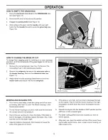
Page 11: ...cut the grass again You can also cut at 1 2 to 2 3 of the full cutting width of the mower housing HOW TO CLEAR THE CONNECTOR TUBE AND THE EXTENSION TUBE if the connector tube or the extension tube becomes filled with grass clear as follows 1 Move the attachment clutch lever to the DISENGAGE posi tion see Figure 13 2 Move the shift lever to the neutral N position 3 Engage the parking brake see Figu...

Page 12: ...sion Mower Housing Tube Figure 17 MOWING AND BAGGING TIPS 1 For a lawn to look better check the cutting level of the mow er housing See How To Level The Mower Housing in the Maintenance section 2 3 4 For the mower housing to cut level make sure the tires have the correct amount of air pressure Every time you use the unit check the blade If the blade is bent or damaged immediately replace the blade...

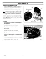
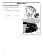
Page 13: ...ector tube must be clean and free from grass and debris Remove and clean the connector tube as follows TO REMOVE 1 Move the attachment clutch lever to the DISENGAGE posi tion see Figure 13 2 Move the shift lever to the neutral N position 3 Engage the parking brake see Figure 14 4 Stop the engine 5 Move the lift lever to the middle cutting position 6 Lift the cover and remove the grass bag assembly...

Page 14: ...nt ing plate see Figure 20 3 Lift the bag mounting plate off of the shoulder bolts 4 Remove the wingnuts that secure the extension tube to the mower housing Remove the extension tube see Figure 21 5 Close the mulch cover 3 and secure with the wingnuts Shoulder Bolts H Studs Bag Mounting Plate Figure 20 Mower Housing Extension Tube Wingnuts Figure 21 F 020902L 14 ...

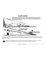
Page 15: ... DEGREES 15 DEGREES Operate a riding mower up or down slopes never across the face of slopes On a riding mower to determine if a slope is safe to mow 1 disengage the blade s 2 put the unit in reverse and 3 try to back straight up the slope If you can back up the slope it is generally safe to mow However if you do not feel safe or you are not completely sure use this guide to determine the slope an...

Page 16: ...MODEL 536 249810 REPAIR PARTS GRASS BAGGER 32 31 12 8 6 14 34 17 15 33 29 3O 9 28 27 25 23 24 23 24 _ 25 9 7 _35 20 21 F O20902L 16 ...

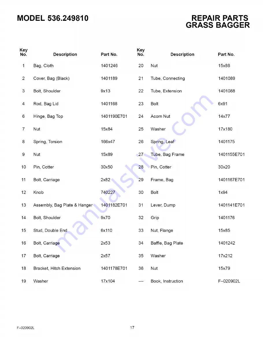
Page 17: ...g Plate Hanger 1401182E701 31 14 Bolt Shoulder 9x70 32 15 Stud Double End 6x110 33 16 Bolt Carriage 2x53 34 17 Bolt Carriage 2x57 35 18 Bracket Hitch Extension 1401178E701 36 19 Washer 17x104 Description Nut Tube Connecting Tube Extension Bolt Acorn Nut Washer Spring Leaf Tube Bag Frame Pin Cotter Frame Bag Bolt Lever Dump Grip Nut Flange Baffle Bag Plate Washer Nut Book Instruction Part No 15x88 ...

Page 18: ...de hierba En el espacio indicado a continuaci6n anote el nQmero de serie y la fecha de compra de la unidad El nQmero de modelo y el nQmero de serie se encuentran en la calcomania ubicada en la parte trasera del bastidor N_mero de Modelo 502 24981 NQmero de Serie Fecha de Compra Guarde estos nQmeros para referencias futuras Felicitaciones por su compra de un aditamento recolector de hierba Craftsma...

Page 19: ...posicion neutro antes de arrancar el motor 17 Siempre use galas de proteccion u algQn tipo de protector para los ojos cuando utilice la unidad de esta manera prote gera sus ojos de objetos que pudieran ser lanzados por la maquina Este tipo de proteccion ocular tambien debe usar F 020902L 19 Io cuando necesite hacer ajustes o reparaciones a la maqui ha 18 Tenga mucho cuidado cuando deba remolcar ca...

Page 20: ...combustible cuando la unidad se encuen tra en un recinto cerrado d Nunca guarde el cortacesped con combustible en el tan que o el recipiente de combustible en un recinto donde haya alguna llama expuesta tal como el piloto de un calentador de agua Nunca arranque el motor ni Io deje en marcha dentro de un recinto cerrado Mantenga todas las tuercas y pernos apretados especial mente las tuercas de mon...

Page 21: ...orto 6 Llave de boca 3 8 1 2 7 16 9 16 de pulgada 7 Se recomienda un juego de vasos BOLSA DE PARTES CONTENIDO Los sujetadores y otras piezas se muestran a continuacion Los sujetadores se ilustran en sus tamafios reales Los nQmeros entre parente sis indican la cantidad Para algunos modelos no se requieren todos los sujetadores 1 Perno 2 Pemo de coche 17x212 17x104 Perno de coche 2 ArandeIa 1 Arande...

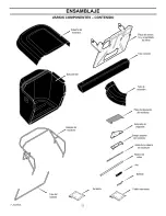
Page 22: ...nsamblado de silleta Tubo conector Bolsadetela Tubode extensi6n Placa de desviaci6n del recolector Bastidordel recolector Extensi6n de enganche Bisagrasuperior del recolector Tubodel bastidor Varillade la cubierta del recolector Asa Ballesta J Tornilleria Folleto informativo F O20902L 22 ...

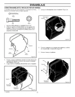
Page 23: ...es abiertos A Bastidor Tubo Bastidor A Tubo inferior Figura 22 Coloque las abrazaderas sobre el bastidor Figura 24 Abrazaderas Bastidor Abrazaderas Figura 24 Coloque la palanca en el soporte de la palanca y sujetela con el perno B y la tuerca C Figura 25 7 Coloque el asa en la palanca 3 Primero coloque la abertura ubicada en el lado derecho del recolector de hierba en posici6n para aceptar el sopo...

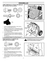
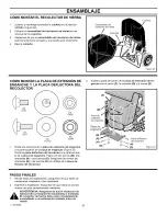
Page 24: ...olector a los tornillos prisioneros Pernos Placa de mont_e deI recolector Tornillos H prisioneros Figura 27 COMO MONTAR LA CUBIERTA DEL RECOLECTOR DE HIERBA 2 L 15x84 Para montar la cubierta deslice el agujero de pivote izquierdo sobre el extremo izquierdo de la varilla de articulaci6n Deslice la cubierta hacia la derecha Figura 28 Deslice el agujero de pivote derecho sobre el extreme derecho de l...

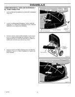
Page 25: ...rdetcoRac6sped Tubo de extensidn Tuercas de mariposa Figura 29 3 4 Deslice la seccion recta del tubo conector a traves del es pacio de la placa de montaje del recolector Figura 30 AsegOrese de que el simbolo de seguridad en el tubo co nector este orientado hacia afuera y sea visible Deslice el extreme del tubo conector dentro del tubo de extensi6n Figura 31 Instale la ballesta en el agujero del tu...

Page 26: ...a de extensi6n de enganche a la parte superior de la placa de enganche Figura 33 Monte la placa deflectora del recolector a la parte de aba jo de la placa de enganche Fijela con dos pernos M dos arandelas N y dos tuercas O Aseg0rese de montar las arandelas N y las tuercas O pot debajo de la placa de flectora del recolector P Placa de extensi6n de enganche Placa de enganche _ Q R Placa deflectora N...

Page 27: ...ici6n mas alta Luego baje el carter del cortacesped y vuelva a cortar Tam bien puede cortar de 1 2 a 2 3 del ancho completo del c rter del cortacesped COMO DESPEJAR EL TUBO CONECTOR Y EL TUBO DE EXTENSION Si el tubo conector o el tubo de extensi6n se llenara de hierba limpielo de la manera siguiente 1 Mueva la palanca de embrague de aditamentos a la posici6n DESENGANCHADO Figura 34 2 Mueva la pala...

Page 28: ...iposa Figura 38 CONSEJOS PARA EL CORTE Y LA RECOLECCION 1 Para mejorar la presentaci6n del cesped verifique el nivel de corte del carter del cortacesped Consulte Como nivelar el c rter del cortacesped en la seccion de Mantenimiento 2 3 Para asegurar un nivel de corte parejo compruebe que los neumaticos tengan una presi6n de aire adecuada Antes de cada uso examine la cuchilla Si la cuchilla est dob...

Page 29: ...ar limpio y sin restos de hierba cortada o basura Retire y limpie el tubo conector de la manera indicada a continuaci6n PARA RETIRAR EL TUBO CONECTOR 1 Mueva la palanca de embrague de aditamentos a la posici6n DESENGANCHADO Figura 34 2 Mueva la palanca de cambios a la posici6n neutro N 3 Enganche el freno de mano Figura 35 4 Apague el motor 5 Mueva la palanca de elevaci6n a la posici6n de corte de...

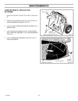
Page 30: ... y saque la placa de montaje del recolector de los pernos de tope 4 Quite las tuercas de mariposa que fijan el tubo de exten si6n al c_rter del cortac6sped Quite el tubo de extensi6n Figura 42 5 Cierre la cubierta para trituradora e instale de nuevo las tuercas de mariposa Pernos de tope Tornillos H prisioneros PIaca de montaje det recolector CaRerdetcoRac6sped Tubo de extensi6n Figura 41 Tuerca d...

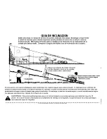
Page 31: ...uentra en el tractor cortacesped y quiere determinar si la cuesta es segura para cortar el cesped 1 desenganche la cuchilla s 2 ponga la unidad en marcha atras y 3 trate de retroceder en subiendo la cuesta en forma directa Si puede subir retrocediendo esto indica que generalmente el seguro cortar el cesped a ese grado de inclinacion Sin embargo si usted no se siente seguro o no esta completamente ...

Page 32: ...iiiii ii_i_ii i i i_ For the replacement parts accessories and owner s manuals that you need to do it yourself call Sears PartsDirect sM 1 800 366 PART 6 a m 11 p m CST 1 800 366 7278 7 days a week www sears com partsdirect To purchase or inquire about a Sears Service Agreement 1 800 827 6655 7 a m 5 p m CST Mon Sat Para pedir servicio de reparaci6n a domicilio y para ordenar piezas con entrega a ...

Reviews: