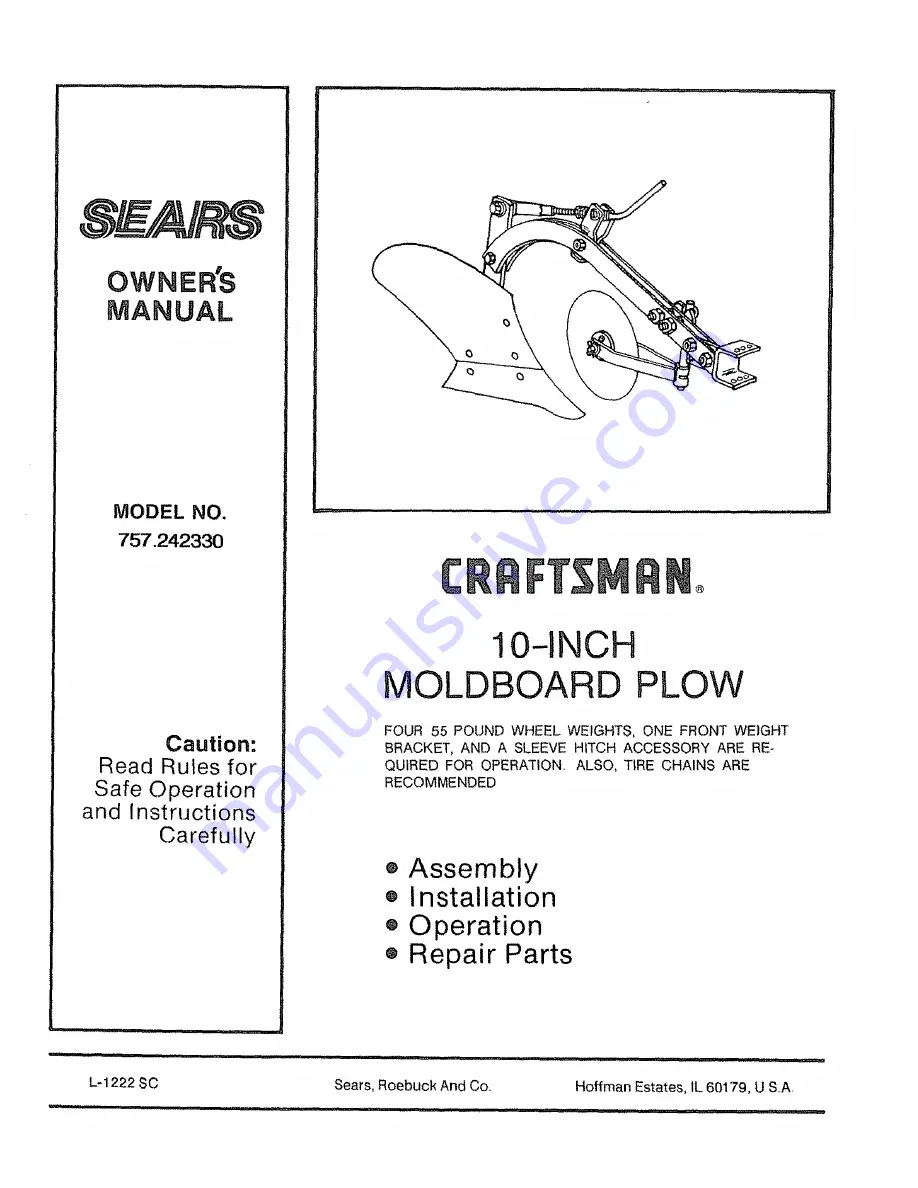
background image

Summary of Contents for 757.242330

Page 1: ...LOW FOUR 55 POUND WHEEL WEIGHTS ONE FRONT WEIGHT BRACKET AND A SLEEVE HITCH ACCESSORY ARE RE QUIRED FOR OPERATION ALSO TIRE CHAINS ARE RECOMMENDED Assembly Installation Operation Repair Parts it i n inlll l l 11 1 ilU irll nl L 1222 SC Sears Roebuck And Co Hoffman Estates tL 60179 USA ilU i i i lit i lU i lU l i lUUl i ...

Page 2: ...ction and without having read the owner s manual o Do not carry passengers Keep children and pets a safe distance away Always wear substantial footwear Do not wear loose fitting clothing that can get caught in moving parts Keep your eyes and mind on your tractor attach ment and area being covered Don t let other interests distract you e Stay alert for holes in the terrain and other hidden hazards ...

Page 3: ...ASE AND KEEP IN A SAFE PLACE FOR FUTURE REFERENCE CUSTOMER RESPONSIBILITIES e Read and observe the SAFETY RULES e Follow a regular schedule in maintaining caring for and using your Plow TABLE OF CONTENTS WARRANTY 2 PLOWING TIPS 8 SAFETY RULES 2 ADJUSTMENTS 8 9 CARTON CONTENTS 3 4 5 CUSTOMER RESPONSIBILITY 9 ASSEMBLY 5 6 TROUBLE SHOOTING 0 OPERATION 7 8 REPAIR PARTS 11 CONTENTS OF SHIPPING CARTON N...

Page 4: ...her 1 2 Flat Washer 5 8 3 Used 1 Used 2 Used Z 1216 B HARDWARE BAG No 7 P_234 Spacer II2 tD xgi16 Used No 14 P 262 01 Spacer 5 8 1D 518 1 Used No 2 B t677P Hez Lockl Nut 1 2 3 Used No 33 I5M1216 R No 31 10M1012P No 17 P 270 PIow Bolt Carriage Bolt No 32 10MI624P Drive Pin 3 8 x I 5 16 x 3 Carriage 8olt 5 16 xlqi4 2 Used 3 Used 1 2 x 1 2 1 Used t Used No 38 30M1600P Hex Nut 1t2 i__ _ No 41 35M1600P...

Page 5: ...nd insert crank through the hole in SIDE of trlJnnion through spacer the two 5 8 jam nuts and then thread into the threaded tube e Thread one jam nut against the spacer just enough to eliminate any excessive movement of the crank against the trunnion taking care NOT to bind crank o Using two wrenches lock the other jam nut against the first e Before assembling the hitch bracket BETWEEN both beams ...

Page 6: ...by inserting the axle through one leg of the fork the coulter hub and other leg of fork Secure with the two 5 8 flat washers and 1 8 x 1 1 4 cotter pin bend the legs over e Attach the coulter assembly to the plow beam as shown using the U bolt coulter clamp two spacers locate BETWEEN the plow beams and secure with two 5 8 hex nuts Q Position the coulter standard between the U bolt and coulter clam...

Page 7: ...o C Make sure the Tractor Lift Handle is Lowered and Locked into the down position Plow in Third Gear and near Full Throttle Raise the Plow to the Transport Position when turning e If your Plow is not plowing at 4 to 5 deep on your initial two passes readjust the Plow Depth Crank by turning it clockwise e to go deeper or counter clockwise e_ to go shallower See Fig 8 Make this adjustment ONE TURN ...

Page 8: ...and the dirt is apt to be thrown rather than rolled over TRACTION eFour 55 lb weights are required Refer to diagram for positioning them See your local Sears Store or Catalog outlet for purchase of weights e Tire Chains Tire Chains or Rear Chevron Tires Agricultural Tires are also recommended with the plow Again see your local Sears Store or Catalog Outiet or refer to your Tractor Owner s Manual f...

Page 9: ...plowing 8 to 10 wide LIFT ASSIST ADJUSTMENT m Standard _4 _ _ _ndside Tracking Adjusting Bolt FIG 9 Raise the Tractor Lift Handle to Transport in order to adjust the Spring to decrease lift effort of the Attachment o Loosen the Hex Jam Nut against the Spring Bushtng Turn Adjusting Bolt clockwise _ until the washer is flush with Hitch Bracket This extends spring and reduces lift effort Retighten Ja...

Page 10: ...used to polish bottom Or rub with a rag soaked in oil and dipped in sand i i n i UNEVEN PLOWING DEPTH e Extreme variations in soil texture and or moisture Plow rides up in harder dry soil runs shallow See plowing tip Soil too wet or dry Reduce tractor speed in hard spots Check Depth Adjustment e Plow goes too deep i i 1111 _lnl Check Depth Adjustment Turn Counter clockwise HOW TO ORDER REPAIR PART...

Page 11: ... 1 38 Coulter Standard 1 39 Pin 5 16 x 1 I 4 1 40 Coulter Blade 1 41 Frog 1 42 Share I0 1 43 Moldboard 10 t 44 Landside 10 t 45 U Bolt 1 46 47 48 tl I 22 t 18 Part No P 387 01 P 596 10 P 597 P 598 01 M1624P 1Mt628P 1M2032P t0Mt012P 10M1624P 15M1216 R 15M1416P 15Mt 632P 30M 1200P 30M 1400P 30M 1600P 30M2000P 31M2000P 35M t600P 45M1111P 45M1313P 45M1717P 45M2121P 50M0420P L 1222 SC B 4836 t5 Descrip...

Reviews: