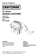
background image

Summary of Contents for 917.249398

Page 1: ...483 and 917 249398 CAUTION Read and follow all Safety Rules and Instructions be fore operating this equip ment Safety Assembly Operation Customer Responsibilities Repair Parts Sears Roebuck and Co Hoffman Estates IL 60179 Visit our Craftsman website www sears com craftsman ...

Page 2: ...or wheel weights or counterweights to improve stability Use extra care with grass catchers or other attachments These can change the stability of the machine Keep all movement on the slopes slow and gradual Do not make sudden changes in speed or direction Avoid starting or stopping on a slope Iftires lose traction disengage the blades and proceed slowly straightdown the slope DO NOT Donot turn on ...

Page 3: ...o stop or shift while on the slope Avoid starting or stopping on a slope If tires lose traction disengage the blades and proceed slowly straight downthe slope Ifmachine stops while going uphill disengage blades shift into reverse and back down slowly Do not turn on slopes unless necessary and then turn slowly and gradually downhill if possible I Look for this symbol to point out important safety p...

Page 4: ...ill repair free of charge any defect in material or workmanship This warranty does not cover Expendable items which become worn during normal use such as bags or mower blades Repairs necessary because of operator abuse or negligence includingthe failure to maintain the equipment according to instructions contained in the owner s manual Grass catcher attachments used for commercial or rental purpos...

Page 5: ...NS Remove all parts and packing materials from carton Foldflaps to insideof carton andturncarton upsidedown on floor of work area To protect grass catcher cover duringassembly place coverupsidedown onoverturned carton Check carton contents against list Be sure all parts are there CARTON CONTENTS 2 Container Tops 2 Container Bottoms 1 Upper Chute 1 Lower Chute 1 Support Post 1 Mounting Bracket 1 Co...

Page 6: ...D I 1 Retainer Spring 1 Bracket Support Pin 3 Tubing End Caps GROUP E J 1 Washer 13 32 x 1 x 16 Ga GROUP F liltltlElllfllllllltltllltltltliltllltltltill I 1 Screw 10 x 1 1 8 1 Spacer Split 10 2 Washer 3 16 x 3 4 x 16 Ga GROUP G J 1 Screw 10 x 5 8 1 Washer Lock 10 1 Washer 3 16 x 3 4 x 16 Ga 1 Wing Nut 1 Nut Acorn 10 1 Rubber Latch 1 Nut Weld 10 6 ...

Page 7: ...OWER CHUTE WING NUT NOTE When right hand R H and left hand L H are mentioned in this manual it means when you are seated on the tractor in the operator s position 1 3 8 Wrench THESE ARE THE TOOLS YOU WILL NEED TO AS 1 _1 2 Wrench SEMBLE YOUR GRASS CATCHER 2 9 16 Wrenches 1 1 2 Socket 1 9 16 Deep well Socket 1 Drive Ratchet 1 3 or longer Extension J Short Handle Phillips Screwdriver A CAUTION BEFOR...

Page 8: ...Iocknuts SELFTAPPING SHOULDER BOLTS See Fig 2B Using the four formed holes in the drawbar install the four shoulder bolts as shown and tighten securely Hang the mounting bracket lanced tabs towards bottom on the bolts _ _ UPPER CORNER UPPER CORNER _ _ _ _ _ _ RI BS RIBS SELF I rr_ TAPPING I L _ _ SHOULDER_ BOLTS _ I LANCEDTABS TOWARD BOTTOM FIG 2B BOLTS AND LOCKNUTS See Fig 2C IMPORTANT ONTRACTORS...

Page 9: ... place support post inside mounting bracket Allow assembly to rest on lanced tabs of mounting bracket Line up holes in mounting bracket with holes in support post and insert bracket support pin Secure with retainer spring Unlatch and open cover Install the three 3 tubing end caps onto container support Tap each end cap onto container support tubes to seat securely BRACKET SUPPORT PIN COVER ASSEMBL...

Page 10: ...NG LOWER CHUTE See Fig 8 Use Hardware GROUP E Raise and hold deflector shield in upright position Slide back edge of chute over rear corner of mower deck and pivot forward Align slot in lower chute with hex bolt in mower deck baffle and close chute over deck openning Secure with washer and wing nut CAUTION Do not remove discharge guard from mower Raise and hold guard when attaching lower chute and...

Page 11: ... chute until it is in line with lower chute Align the bosses on lower chute with alignment slots on upper chute and slide together Secure with rubber latch by hooking hole in latch over latch pin FULBAG HANDLE UPPER INDICATOR CHUTE COVER LOWER CHUTE FIG IOA ALIGNMENT SLOTS LATCH PIN RUBBER LATCH BOSSES FIG lOB 1LEVEL MOWER DECK No hardware required Be sure deck is properly leveled for best mower p...

Page 12: ...t tubes Avoidcuttingwet grass or in the morning while the dew is still heavy Grass clippings collected under these conditions tend to be sticky and adhere to the walls of the flow path causing clogging Your bagger is equipped with a full bagger indicator Movement of the wheel increases as the bags fill The wheel will be spinning fastest just before the bags fill completely When the wheel stops it ...

Page 13: ...storing Failure to do so may result in spontaneous combustion which could develop into a fire A CAUTION BEFORE PERFORMING ANY MAINTENANCE SERVICE OR ADJUST MENTS Depress clutch brake pedal fully and set parking brake Place gearshift motion control lever in NEUTRAL position Place clutch control in DISENGAGED position Turn ignition key to OFF position Make sure blades and all moving parts have compl...

Page 14: ...s Catcher you may need 1 Heavy Shears or 1 Hand Saw 1 Ruler 1 Drill Motor 1 9 32 Drill Bit 1 11 32 Drill Bit 1 13 32 Drill Bit 2 7 16 Wrench 2 1 2 Wrench 1 9 16 Wrench A socket wrench set will make assembly easier Standard wrench sizes are listed TRIM DEFLECTOR SHIELD See Fig 11 On some model tractors it may be necessary to trim the bottom corner of the deflector shield If your deflector shield is...

Page 15: ...r Tape in position Mark and drill hole 1 only using a 11 32 drill bit Assemble mounting bracket to drilled hole indrawbar with one hex bolt and nut from hardware group B NOTE Mounting bracket must be assembled with lanced tabs to bottom as shown HEX BOLT DRAWBAR AND NUT L __ MOUNTING B ACNET I IO I IO h _ Ii Ii Ii II Ii t_ LANCED TABS TO Bo3 rOM WIRE LOOP MOUNTING HOLE drill 9 32 if necessary _ PA...

Page 16: ...16 ...

Page 17: ...EFLECTOR TRIM DEFLECTOR ALONG DOTTED LINE USING EITHER HEAVY SHEARS OR A HAND SAW 17 MOWER DECK BAFFLE DRILL TEMPLATE TOP EDGE I I I I I i 2 I I R 1 I II I G i 1 I I 1 t 4 _ USE TEMPLATE ABOVE FOR A GUIDE TO DRILLING YOUR MOWER DECK BAFFLE CUT OUT SHADED AREA AND ALIGN WITH TOP AND RIGHT EDGE OF BAFFLE DRILL A 13 32 HOLE AT SPECIFIED LOCATION ...

Page 18: ...18 ...

Page 19: ...OF TEMPLATE AND DRAWBAR I I I II I USE 11 32 DRILL BIT WIRE LOOP HOLE rkl_W USE 9 32 DRILL BIT _ i_ _l 3 TAPE IN POSITION 4 MARK AND DRILL HOLE 1 5 ASSEMBLE MOUNTING BRACKET TO DRAWBAR USE BRACKET AS TEMPLATE FOR REMAINING HOLES I f I I WIRE LOOP HOLE I OLD I I I f I I I r i e _ L 7 _ _ _ _ _ _i d i i iI ...

Page 20: ...20 ...

Page 21: ...21 ...

Page 22: ...REPAIR PARTS GRASS CATCHER MODEL NUMBER 917 249483 AND 917 249398 2 _ 4 5 20 38 2 39 2 33 20 2O 12 9 21 24 15 10 17 18 36 31 31 40 26 b 27 41 _ 26 25 ...

Page 23: ...upport Post 9 19061216 Washer 3 16 x 3 4 x 16 Ga 31 174083 Plug Tubing End 10 7206J Spacer Split 32 126919X Bagger Frame 11 STD541810 Nut Acorn 10 34 33 128600 Pin Hinge 12 STD551110 Washer lock 1q 34 127534 Gasket Cover 13 109808X Latch Chute 35 183286 Container Top 14 2029J Nut Weld 36 129586 Container Bottom 15 74930620 Bolt Hex 3 8 16_ 1 1 4 38 130895 Latch Handle Cover 16 19131616 Washer 13 3...

Page 24: ...or go on line for the nearest Sears Parts and Repair Center 1 800 488 1222 Anytime day or night U S A only www sears com To purchase a protection agreement U S A or maintenance agreement Canada on a product serviced by Sears 1 800 827 6655 u s_ 1 800 361 6665 Canada Para pedir servicio de reparacibn a domicilio y para ordenar piezas 1 888 SU HOGAR si 1 888 784 6427 Au Canada pourservice en franc _...

Reviews: