background image

Summary of Contents for 917.254244

Page 1: ...ead and Follow All Safety Rules And instructions Before Operating This Equipment LT 12 HP ELECTRIC START 6 SPEED 38 MOWER LA WN TRA CTOR Assembly Operation e Maintenance Repair and Adjustment Repair Parts Sears Roebuck and Co Chicago IL 60684 USA ...

Page 2: ...the vehicle while in operation 26_ Handle gasoline with care it is highly flammable a Use approved gasoline containers o b Never remove the fuel cap of the fuel tank or add gasoline to a running or hot engine or an engine that has not been allowed to cool for several minutes after running Never fill tank indoors always clean up spill ed gasoline c Open doors ff the engine is run in the garage exha...

Page 3: ...rs from date of purchase when this riding equipment is maintained lubricated and tuned up according to the operating and maintenance instruction in the owner s manual Sears will repair free of charge any defect in material or workmanship in this electric start ridino eouiom_m This warranty excludes blade s blade adapterls spark pluglsl air cleanerlsl and beltlel which are expen dable and become wo...

Page 4: ... 16 Air Screen 16 Battery 15 Blade Sharpening 14 Brake Adjustment 14 Engine Oil 16 Lubrication Chaff 24 Spark Plugs 18 Tire Care 14 Mower Adjustment Front to Rear 23 Adjustment Side to Side 22 Blade Sharpening 14 Blade Replacement 14 Cutting Level 12 Installation 21 Operation 11 Removal 20 Muffler 17 Spark Arrester 2 0 Oil Cold Weather Conditions 16 Engine 16 Storage 23 Operation 9 12 Operating Yo...

Page 5: ...g Sleeve with tab on steering bushing 8 Place steering wheel adapter on upper steering shaft 9_ With front wheels pointed straight ahead place steering wheel on steering wheel adapter Bars of steering wheel should point straight across tractor 10 Place 2 1 4 diameter washer on upper steer ing shaft and install a 1 2 Iocknut washer and Iocknut found in bag of parts Tighten secure ly 11 Snap insert ...

Page 6: ...ckwasher I 4 Int Ext Tooth 2 Wing Nut _ 1 4 20 m 2 Hex Bolt I 4 20 x 3 4 P_ 2 Lockwasher 1 4 2 Washer 9 32 x 5 8 x 16 Ga 2 Hex Nut 1 4 20 1 Hex Bolt 1 2 13 x 1 Grade5 1 Shoulder Bolt S 16 18 Q J Lockwashet 1 2 I Washer 15 32x 1x 16 Ga 1 Washer 17 32x I 3 16 x 12 Ga 2 Hex Bolt 3 8 16x 1 I 4 2 Flex Locknut 3 8 16 Dia Washer 1 Locknut 1 2 20 ...

Page 7: ...tery with water to remove any acid then wipe dry d Check battery case for leakage to make sure that no damage has occured in handling c e Neutralize excess battery acid for disposal by adding it to four inches of water in a five gallon plastic d container Stir with a wooden or plastie paddle while adding baking soda until the addition of more soda causes no more foaming _ e L Use a 12 volt battery...

Page 8: ...attery terminal with remaning hex bolt flat washer lock washer and hex nut shown full size on pg 6 found in bag of parts Tighten securely Fig 4 e To prevent corrosion apply grease to the battery terminals after installing cables L Usingthekeyholeononesideof_ebatterysupport Fig 5 slide battery boll into frame key hole head of boll down Fasten the battery bolt to the terminal guard using internal ex...

Page 9: ...achment mounted to your tractor Pull lever back slightly and push button then move the rift lever forward to lower attachment CLUTCH BRAKE PEDAL The pedal has 2 functions a clutch and a brake To engage the brake push the pedal completely down ATTACHMENT HEIGHT ADJUSTMENT KNOB Use the height adjustment knob to adjust the mower heighL With the attachment lift lever in the tJp positiono turn knob clo...

Page 10: ...pped filled with summer weight oil For cold weather operation see chart page 16 Check engine oil level Refer to REPAIR AND ADJUSTMENT section page 161o b Fill fuel tank Fig 6 Use fresh clean regular unleaded gasoline Capacity is 5 quarts FILL TO BOTTOM OF GAS TANK FILLER NECK DO NOT OVERFILL WIPE OFF ANY SPILLED OIL OR FUEL DO NOT STORE SPILL OR USE GASOLINE NEAR AN OPEN FLAME CAUTION EXPERIENCE I...

Page 11: ... in place and working 4 Remove objects that can be thrown by blades 5 Do not mow when children and others are around 6 Never carry children or passengers 7 Always look behind machine before backing 8 Do not mow where machine can tip or slip 9 If machine stops going uphill stop blades and back slowly clown 10 Be sure blades and engine have stopped before placing hands or feet near the blades 1I Rem...

Page 12: ...large areas Fig 9 start by turning to the right so that the clippings will discharge away from shrubs fences driveways etc After two or three rounds mow in the opposite direction making left hand turns until finished e ff grass is extremely tall it should be mowed twice The first time cut relatively high the second time to the desired height f The left hand side of mower should be used for trimmin...

Page 13: ...SHUT OFF THE ENGINE 6 MAKE ABSOLUTELY SURE THE BLADES AND ALL MOVING PARTS HAVE COMPLETELY STOPPED_ 7 DISCONNECT THE SPARK PLUG WIRE FROM THE SPARK PLUG AND KEEP WIRE AWAY FROM THE SPARK PLUG TO PREVENT INJURY FROM ACCIDENTAL STARTING BE CAREFUL TO AVOID TOUCH ING HOT ENGINE OR MUFFLER COMPONENTS SERVICE RECORD Enter Date Maintenance Performed SERVICE RECORD Fill in dates as you complete regular s...

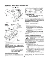
Page 14: ...ing wheel We suggest they be sharpened after every 25 hours of mowing Do not attempt to sharpen while on mower If you mow in sandy soil check the blades after each two mowings The sand wears the blade away rapidly A GRADE 5 HEAT TREATED BOLT CAN BE IDENTIFIED BY THREE LINF _ ON THE BOLT HEAD AS SHOWN AT LEFT a Blade Replacement Raise mower to highest position to permit access to blades 1 Remove th...

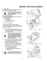
Page 15: ... ff necessary Clean Battery and Terminals Corrosion and dirt on the battery and terminals cause the battery to leak power and hinders the operation of the charger LEAD ACID BATTERIES GENERATE EXPLOSIVE GASES KEEP SPARKS FLAME AND SMOKING MATERIALS AWAY FROM BATTERIES ALWAYS SHIELD YOUR EYES AROUND BATTERIES a Remove terminal guard b Disconnect BLACK battery cable then RED battery cable and remove ...

Page 16: ...OT OVERFILL Dipstick assembly must be securely tightened into tube at all times when engine is operating IMPORTANT TO AVOID DAMAGE TO THE STARTING SYSTEM USE SAE 5W30 OIL WHEN THE TEMPERA TURE FALLS BELOW 32 Recommended SAE Viscosity Grades Determine temperature range expected before next oil change_ A oil must meet A PJ service classification SD SE or SF_ 8 Clean Air Screen and Engine Cooling Fin...

Page 17: ...LTNEGATIVE GROUNDED SYSTEM LEAD ACID BATTERIES GENERATE EXPLOSlVEGASES KEEPSPARKS FLAME AND SMOKING MATERIALS AWAY FROM BATTERIES ALWAYS WEAR EYE PROTECTION WHEN AROUND BATTERIES a Connect each end of the RED cable to the POSI TIVE terminals of each battery taking care not to short against chassis Fig 17 b Connect one end of the BLACK cable to the NEGATIVE terminals of fully charged battery c Conn...

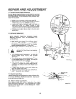
Page 18: ...rt engine and allow to idle for five minutes REFER TO STARTING THE ENGINE PAGE 10_ c Turn mixture screw clockwise _k until the engine speed drops NOTE THE SCREW POSITION d Turn mixture screw counterclockwise Ir_ un til the engine begins to run rough Set mixture screw between the two positions e Push throttle lever to FAST detent not CHOKE If engine runs rough make small ad justments on mixture scr...

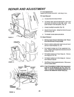
Page 19: ...t guides away from belt toward rear of tractor Fig 21 _ d Roll belt over top of transaxle pulley e Roll belt over engine pulley and off idler Fig 22 f Release parking brake Pull belt as far as possible over top of clutch pulley g Reset parking brake Pull belt over top of clutch pulley Fig 22 h Pullbelt out through shift gate to remove from tractor Fig 23 Install belt by reversing above procedure B...

Page 20: ...s under Mower Drive Belt Removal through step c b Remove retainer spring from clutch rod pull clutch rod out of clutch brackeL Fig 26 c Puff retainer springs out of fear suspension trun nions Remove rear suspensions trunnions from lift brackets Fig 26 d Pull retainer spring out of rear hinge pin Remove rear hinge pin Fig 26 e Pull retainer spring out of front hinge pin_ Remove front hinge pin Figo...

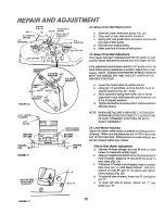
Page 21: ...des Fig 28 See belt drive sche matl_ decal on mower housing g Use Attachment lift lever Fig 27 to raise mower h Turn height adjustment knob clockwise _ to the middle of its travel or to desired cut height Fig 28 LIFT LEVER PLUNGER LIFT LEVER POSITION FIGURE 2 7 ENGINE_ IELT PULLEY 2 I Mower Drive Belt Removal NOTE MOWER BELT INSTALLATION DECAL LOCATED ON MOWER HOUSING REPLACE ONLY WITH THE BELTS S...

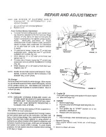
Page 22: ...ut the D shaped washers d TightenboltandnuttosecuretheD shapedwashers flat side down LIFT PLUNGER LIFT LEVER BOTTOM OF CURL SIDE TO SIDE BOTTOM CURL NOTE WHEN INSTALLING A NEW BELT EXTENSION SPRING MUST BE RETURNED TO LOWER END OF SLOT ORIGINAL POSITION ON ROCK SHAFT ASSEMBLY 24 Level Mower Housing Adjust the mower while tractor is parked on level ground or driveway Make sure tire pressures are 14...

Page 23: ...e in a clean dry area o T GROUND LINE REAR SUSPENSION _ ARM OF CURL REAR SUSPENSION TRUNNION __ EAR SUSPENSION REAR NUT E RM SU _ENSION_ TRUNNION LIFT NUT_ F BRACKET GROUND LINE _GURE 33 RGURE 34 A Fuel System NOTE GASOLINE STORAGE STABILIZER SUCH AS STA BIL MUST BE ADDED TO GASOLINE WHEN STORING UNIT SUCH AN ADDITIVE WILL MINI MIZE FUEL GUM DEPOSITS PREVENTING A CLOGGED FUEL SYSTEM Run engine 10 ...

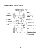
Page 24: ...NT WHEEL BEARING CLUTCH BRAKE PIVOT _ _ ATTACHMENT LIFT_ _J ARM AXLE PIVOT SPINDLE _1_ _FRONT WHEEL BEARING CLUTCH PIVOT _ ATTACHMENT LIFT ARM MOWER CLUTCH PIVOT SAE 30 MOTOR OIL _ GENERAL PURPOSE GREASE REFER TO PAGE 16 FOR ENGINE OIL SPECIFICATIONS 24 ...

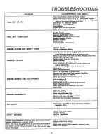
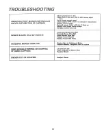
Page 25: ...ngaged will shut down the engine Piece Throttle Control in FAST position and run starter several times to clear out gas Remove and clean Fuel Tank and lines Replace Fuel Filler Remove Air Filter and clean Replace Spark Plug and adjust gap Replace Battery Check the wiring and Spark Plug Drain Fuel Tank and Carburetor use fresh fuel and replace Spark Plug Make necessary adjustments to Carburetor Adj...

Page 26: ...op of blade up Replace with proper mower blades Re adjust mower drive belt Install new Mower Drive Belt Reinstall Mower DHve Belt MOWER BLADES WILL NOT ROTATE Adjust Mower Drive Belt Replace Frozen Mandrel Replace Frozen Idler Pufloy Replace Bent or Unbalanced Blades EXCESSIVE MOWER VIBRATION Replace Mandrel Straighten Deck or replace WIND ROWING STRIPPING OR DROPPING Let grass dry out Clean under...

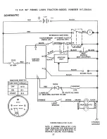
Page 27: ...PEDAL UP CLUTCH OFF I I I WH TE __ s BLACK SEAT _ t SWITCH _ _J IGNITION L NOT OCCUPIED BLACK_ UNIT F BLACK GO _I RED BLACK O O BLACK SPARK PLUG DIODE __2 CHARGING COIL 0 3 AMPS DC VOLTS AC MINI AT 3600 RPM BATTERY IN LINE ORANGE LIGHT Z I _ I v SW TCH _ol HEA_HTS I_ WIRING INSULATED CLIPS NOTE IF WIRING INSULATED CLIPS WERE REMOVED FOR SERVICING OF UNIT THEY SHOULD BE REPLACED TO PROPERLY SECURE ...

Page 28: ...T n LLI rn Z I ILl I Q 0 i D I J z wl n co n 3 qp m I IJJ LU i _ IlL 28 t_ T_ ...

Page 29: ...E i W m I ttl o I 0 F I m J l J W J W Z o O h _0 o Z Z o O U w D wO _Z a wO vz _8 TM _ X_O_ _m_mm_moo XxXXX _ x__ 8 8 _ o_O_ LO _ _ _ X o _ _ _ _ _ _ 2g ...

Page 30: ...a _ w z ft w 30 ...

Page 31: ... D iii iii Z J I 0 F z z CO LU I 0 J _J z iii F Q E W _d D LU F D _z 0 31 ...

Page 32: ...REPAaR PARTS 12 H P 38 RIDING LAWN TRACTOR MODEL NUMBER 917 254244 DRIVE P F Q KK N 3 32 22 21 102 OPTIONAL EQUIPMENT Spark Arrester Screen Assembly ...

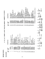
Page 33: ...Ga Knob Shift Rod Shift Bolt Flex I 4 28 x 3 4 Washer Shift Plate Cotter Pin I B x I Washer 15 32 x 3 4 x 16 Ga Retainer Belt Screw Hex Washer Thd Rolling 3 8 16 x 3 4 Washer 13 32 x 13 16 x 12 Ga Keeper Belt Engine 49 109070X Retainer Belt 50 4470J Spacer 5 f 4859J Idler Flat 52 106298X Pulley Idler 53 t 05705X Bellcrank Assembly inc Key No 88 54 STD523715 Bolt Hex 3 8 16 x _ I 2 55 I05709X Sprin...

Page 34: ...REPAIR PARTS 12 H P 38 RIDING LAWN TRACTOR MODEL NUMBER 917 254244 I ...

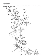
Page 35: ...ead Rolling 3 8 16 x 3 4 Type TT Bearing Thrust Gear Sector Key Woodruff Klip Ring Washer Hardened Shaft _Steering Lower 34 2882J 35 74580 36 71208 37 I08683X 38 105663X 39 I05664X 40 74761060 41 105669X 43 11043BX 44 73901000 45 17490508 46 I08685X 47 3366R 48 105715X 49 120382X 50 19131416 51 76020412 52 STD551137 53 STD541137 54 I05727X 55 I05656X 56 105654X 57 278H 58 9040H 59 I06732X 60 59192...

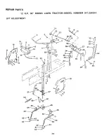
Page 36: ...REPAIR PARTS 12 H P 38 RIDING LAWN TRACTOR MODEL NUMBER 917 254244 LIFT ADJUSTMENT 16 53 3O IB B C 36 ...

Page 37: ...1X Panel Dash R H 50 76020412 19292016 Washer 29 32 x 1 1 4x 16 Ga 51 I06446X 12000022 ERing 52 19131410 100734K Knob 53 6320R STD541237 Nut Flex Jam 3 8 16 54 105764X 1I0809X Red Adjust Lift 76020308 Pin Cotter 3 32 x 1 2 55 I05767X 2876H Spring 56 I06810X 19131016 Washer 13 32 x 5 8 x 16 Ga 57 72140606 110810X Trunnion Depth Stop 58 I08236X 19151216 Washer15 32x3 4x16Ga 59 110807 12000037 Klip R...

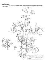
Page 38: ...RTS 12 38 MOWER H P 38 RIDING LAWN TRACTOR MODEL NUMBER 917 254244 1 CC 53 I _45 48 58 59 I 51 5O 33 38 t IF GRASS CATCHER ATTACHMENT IS I BEING USED REFER TO GRASS CATCHER I OWNERS MANUAL FOR BLADE PART NUMBER ...

Page 39: ...Arm Idler 66 STD551037 30 106902X Spacer Retainer 69 19132012 31 102403X Pulley Idler 70 106679X 32 106513X Washer Wear 1 16 71 76020308 33 102669X Keeper Belt 72 72110506 34 10589 IX Mandrel Assembly 73 STD522507 35 I00668L Plate Support Mandrel 74 I09893X 36 17490612 Screw Hex Washer Hd 3 8 16 x 3 4 75 73680400 37 17490620 Screw Flex Washer Hd_ 3 8 16 x 76 19131407 I I 4 77 110445X Blade Washer ...

Page 40: ...REPAIR PARTS 12 H P 38 RIDING LAWN TRACTOR MODEL NUMBER 917 254244 TRANSAXLE FOOTE MODEL NUMBER 4150 40 TRANSAXLE 5O 49 53 54 58 59 60 38 46 65 63 64 66 67 68 40 ...

Page 41: ...60 108989X 23 105916X Ring Retaining 61 110477X 24 110467X Sprocket 18T 62 108991X 25 110070X Spacer 63 108992X 26 108977X Gear Spur 37T 64 110074X 27 109001X Gear Spur 35T 65 108994X 28 108979X Gear Spur 30T 66 108995X 29 10898OX Gear Spur 25T 67 108996X 30 108998X Gear Spur 22T 68 73810500 31 108455X Gear Spur 19T 69 108727X 32 105925X Washer Plain 640 x 1 37 x 061 70 106596X 33 110468X Ass y Ge...

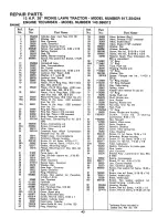
Page 42: ... PARTS ENGINE 12 H P 38 RIDING LAWN TRACTOR MODEL NUMBER 917 254244 ENGINE TECUMSEH MODEL NUMBER 143 386012 MODEL and SERIAL _ 115 NUMBERS HERE 13 6564 81 70 _74 76 134 133 132 131 _121 _ 20 19A I 126 _19 42 ...

Page 43: ...erlok 1 4 20 x 1 3 16 Key Flywheel Flywheel Washer Lock Nut Flywheel Hex 5 8 18 Solid State Assy Cover Spark plug Stud Solid state assy Screw Hex hd Sems 10 24 x 1 Gasket Cylinder head Head Assy Cylinder Valve Guide Kit Inc 2 of No 52 Ring Retaining Ref No 53 53 54 54 55 56 57 58 59 6O 6OA 61 62 63 64 65 66 67 68 69 70 71 72 73 74 75 76 77 79 79 8O 43 81 82 83 84 85 86 87 88 89 90 90A 91 92 93 94 ...

Page 44: ...REPAIR PARTS 12 H P 38 RIDING LAWN TRACTOR MODEL NUMBER 317 254244 ENGINE TECUMSEH MODEL NUMBER 143 386012 ENGINE 81 MODEL andSERIAL NUMBERS HERE 51 ooA 1 18 13 I 1132B 33 44 ...

Page 45: ...r cleaner Screw Hex hd Sems 1 4 20 x 3 4 Coil Assy Alternator 3 Amp D C IncL Nos 152 153 8 154 Diode Connector Body Terminal Female Clip Oil fill tube Clip Wire Screw Hex hd Sems 1 4 20 x 1 2 Decal instruction Carburetor Incl NOr 91 Starter Motor 12 Volt Gasket Set Incl items marked O Ring Kit Incl items marked t RPM Settings Low Speed 1700 High Speed 3500 Indicates Parts Included in Gasket Set Re...

Page 46: ...03 10 33759 11 33712 12 33705 13 33440 14 590500 15 3 3449 16 33706 17 650168 18 650723 19 34685 Part Name Starting Motor Complete Cover Dust Ring Retainer Retainer Spring Spring Anti drift Gear Nut Engaging Nut Lock Cap Assy Drive end Armature Housing Assy Card Assy Brush Incl No 12 Brush 8 Spring Kit Incl 4 pcs of No 13 Spring Brush Washer Thrust Bolt 10 32 x 4 1 4 Cap Assy Commutator end Washer...

Page 47: ...N HILL NOT ACROSS HILL SIGHT AND HOLD THIS LEVEL WITH SKY LiNE OR TREE 15 MAX Operale your Tractor ul awJ down the faoe of slopes no greater than 15 _ never across lh_ face Make tu_r_s g_adLJ alIV to prevent tlpp_f1 J or toss ol control ExercLse _xtref nu caullon when chan jlng Jifect_on On Slopes ...

Page 48: ... any Sears Service Center Departments and most Sears Stores WHEN ORDERING REPAIR PARTS ALWAYS GIVE THE FOLLOW ING INFORMA TION THE PART NUMBER 0 THE PART DESCRIPTION THE MODEL NUMBER THE NAME OF MERCHANDISE Your Sears merchandise has added value when you consider Seers has service units nationwide staffed with Sears trained technicians having the parts tools and the equipment to insure that we mee...

Reviews: