background image

Summary of Contents for 917.255930

Page 1: ... MODEL NO 917 255930 Caution Read and follow all Safety Rules and lnstruchons Before Operating This Equipment Assembly oOperation Maintenance o Service and Adjustment Repair Parts Sears Roebuck and Co Chicago IL 60684 U S A ...

Page 2: ...otiate the slope without stopping Never mow in wet or slippery grass when traction is unsure or at a speed which could cause a skid Stay alert for holes in the terrain and other hidden hazards Keep away from drop offs Do not drive too close to creeks ditches and public high ways Exercise special care when mowing around fixed objects in order to prevent the blades from striking them Never delib era...

Page 3: ...h a spark arrester meeting applicable local or state laws if any If a spark arrester is used it should be maintained in effect ve working order by the operator In the state of California the above is required by law _Section 4442 of the California Pubtic Resources Code Other states may have similar laws Federal laws apply on federal lands A spark arrester for the muffler is available through your ...

Page 4: ...17 Oil Level t3 17 Oil Type t7 Preparation 13 Starting 14 Storage 26 F Filter Air Cleaner 18 Fuel 18 Fuel Storage 26 Type 14 Fuel Type 13 Fuse 23 Headlights 23 Hood Removal 24 Leveling Mower Deck 19_20 Lubrication Chart 15 M Maintenance 15 18 Air Filter 18 Foam Pre Cleaner 18 Air Screen Engine 18 Battery 17 Blade 16 Cooling Fins Engine 18 Engine Oil 17 Fuel Filter I8 Lubrication Chart 15 Schedule ...

Page 5: ...ype auger handles powdery and wet heavy snow Mounts easily with simple pin arrangement Discharge chute adjusts from tractor seat 6 inch diamster spout discharges snow 10 to 50 feet Lift controlled at tractor seat Use with chains wheel weights or rear drawbar weightr TIRE CHAINS are heavy duty closeiy spaced extra large cross links give smooth ride outstanding traction WHEEL WEIGHTS for rear wheels...

Page 6: ...11 32x 1 2 Hex Bolts 1 4 20 x 3 4 2 Hex Nuts t 4 20 2 Washers 9 32 x 5 8 x 16 Ga 2 Lock Washers 1 4 2 Wing Nuts 1 4 20 Parts packed separately in carton m nu n Seat Steering Wheel Battery acid Battery Parts Bag 0wner_s Manual Parts bag contents not shown full size i H u i li i ml 2 Keys 2 Battery Carriage Bolts 1 4 20 x 7 1 2 Steering Wheel Insert 15 Slope Sheet Terminal Guard i 1 Battery Caps and...

Page 7: ... large flat washer from steering shaft Position front wheels of the tractor so they are pointing straight forward Position steering wheel so cross bars are horizontal left to right and slide onto adapter Secure steering wheel to steering shaft with hex bolt lock washer and large fl at washer previously removed Tighten securely Snap insert into center of steering wheel Remove protective plastic fro...

Page 8: ...illed or iron free water Install the vent caps to cover the vent wells Wash the top of the battery with water to remove any acid then wipe dry Check battery case for leakage to make sure that no damage has occurred in handling Dispose of excess battery acid Neutralize acid for disposal by adding it to four inches of water in a five gallon plastic container Stir with a wooden or plastic paddle whil...

Page 9: ...racket Retain with clevis pins and retainer springs SUSPENSION ARM DEPTH ADJUSTMENT KNOB BELT FRONT S1ON BRACKET _ELEASE PIN GAUGE WHEEL BAR _i GAUGE __ _ WHEEL_ _ I_ __ ETAINER FIG 7 DRIVE BELT INSTALLATION See Figs 8 and 9 Remove hood and grill See TO REMOVE HOOD AND GRILL ASSEMBLY in the Service and Adjust ments sections of this manual Roll mower drive beft over primary mandrel Roll mower drive...

Page 10: ...battery bolts remain in slots of the key holes in the battery support Be sure terminal access doors are closed Use terminal access doors for Inspection for secure connections to tighten hardware Inspection for corrosion Testing battery Jumping if required Periodic charging HEX NUT POSITIVE CABLE FLAT HEX BOLT BEFORE YOU OPERATE AND ENJOY YOUR NEW TRACTOR WE WISH TO ASSURE THAT YOU RECEIVE THE BEST...

Page 11: ...Standards Institute ATTACHMENT CLUTCH SWITCH Used to engage mower blades or other attachments mounted to your trac tor LIFT LEVER Used to raise and lower mower deck or other attachments mounted to your tractor CLUTCH BRAKE PEDAL Used for declutching and braking the tractor and starting the engine GEARSHIFT LEVER Selects the speed and direction of tractor THROTTLE CONTROL Used to control engine spe...

Page 12: ...nob out Slowly push knob into disengage TO USE THROTTLE CONTROL See Fig 13 Always operate engine at full throttle Operating engine at less than full throttle reduces the battery charging rate and the engine cooling air flow Full throttle offers the best mower performance TO MOVE FORWARD AND BACKWARD See Fig 13 The direction and speed of movement is controlled by the gearshift lever Start tractor w...

Page 13: ...o ss any slope Choose the slowest speed before starting up or down hills Avoid stopping or changing speed on hills If slowing is necessary move throttle control lever to slower position If stopping is absolutely necessary push clutch brake pedal quickly to brake position and engage parking brake Move gearshift lever to NEUTRAL position To restart movement move gearshift lever to 1st gear and range...

Page 14: ..._ Al ow engine to warm up for a few minutes before engaging clutch brake pedal or attachment clutch switch NOTE If at a high altitude above 3000 feet or in cold temperatures below 32 F the carburetor fuel mixture may need to be adjusted for best engine performance See TO ADJUST CARBURETOR in the Service and Adjustments section of this manual MOWING TiPS Tire chains cannot be used when the mower ho...

Page 15: ...d to operator abuse or negligence To receive full value from the warranty operator must main tain unit as instructed in this manual Some adjustments will need to be made periodically to properly maintain your unit All adjustments in the Service and Adjustments section of this manual should be checked at least once each season Once a year you should replace the spark plug clean or replace air filte...

Page 16: ...deck as shown_ o Reassemble hex bolt lock washer and flat washer in exact order as shown_ Tighten bolt securely 30 35 Ft Lbs torque IMPORTANT BLADE BOLT IS GRADE 5 HEATTREATED BLADE MANDREL ASSEMBLY WASHER LOCK WASHER HEX BOLT S A GRADE 5 HEAT TREATED BOLT CAN BE IDENTIFIED BYTHREE LINES ON THE BOLTHEAD AS SHOWN AT LEFT NTENANCF 11 l Ni _ _ m TO SHARPEN BLADE See Fig 19 Care should be taken to kee...

Page 17: ...vehicle is on level surface Oil will drain more freely when warm Catch oil in a suitable container Remove oil fill dipstick Be careful not to allow dirt to enter the engine when changing oil FILLER CAP DIPSTICK FIG 22 Remove drain plug_ OIL DRAIN P FIG 23 V BELTS Check V Belts for deterioration and wear after 100 hours Replace if necessary The belts are not adjustable Re place belts if they begin ...

Page 18: ...ner with clean engine oil Squeeze in towel to remove excess oil Do not satu rate Install foam pre cleaner over paper cartridge Reassemble cover and screw down tight 18 KNOB COVER NUT WASHER CARTRIDGE PLATE _ CARTRIDGE FOAM PRE CLEANER BODY FIG 26 MUFFLER inspect and replace corroded muffler and spark arrester if equipped as it could create a fire hazard and or damage SPARK PLUGS Replace spark plug...

Page 19: ...ECK ISTO BEMOUNTED ON THETRACTOR REMOVETHE L H AND R H SUSPENSION ARMS AND THE FRONT SUSPENSION BRACKET SIDE TO SIDE ADJUSTMENT See Figs 29 and 30 Raise mower to its highest position SUSPENSION ARM BRACKETS PIN DEPTH ADJUSTMENT KNOB BELT FRONT SUSPEN SION BRACKE1 FIG 29 Measure height from bottom of deck curl to ground level at front corners of mower Distance A should be the same If distance A nee...

Page 20: ...uIley grooves NOTE When installing a new reptacement mower drive belt idler pulley must be moved back to ORIGINAL pulley 3osition BACK D 7 8 TO 1 1 8 FRONT FIG 31 To raise rear of mower loosen nut E on both rear suspension arms Screw both nuts F on both rear suspension arms an equal number of turns When distance D is 7 8 to 1 1 8 higher at rear than front retighten nuts E NUT E ARMS FIG 32 Recheck...

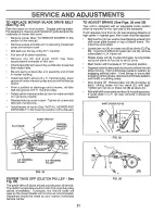
Page 21: ...d with an adjustable brake system which is mounted on the right side of the transaxle If unit requires more than six 6 feet stopping distance at high speed in highest gear then brake must be adjusted Remove four 4 hex washer head tapping screws from shift cover plate located on top of tractor frame_ Re move the cover plate Loosen jam nut A on brake rod B at clevis C Fig 36 If you find it difficult...

Page 22: ...OLT _UIDE FIG 37 FLAT IDLER CLUTCH PULLEY _tj_ 1 11 z_ _ _ _ q V IDLER CLUTCHING IDLER TRANSAXLE PULLEY TO ADJUST STEERING WHEEL ALIGNMENT If steering wheel crossbars are not horizontal left to right when wheels are positioned straight forward remove steering wheel and reassemble per instructions in the Assembly section of this manual FRONT WHEEL TOE IN ADJUSTMENT Front wheel toe in is required fo...

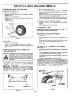
Page 23: ...al of each battery taking care not to short against chassis Connect one end of the BLACK cable to the NEGA TIVE terminal of fully charged battery Connect the other end of the BLACK cable to good CHASSIS GROUND away from fue tank and battery TO REMOVE CABLES REVERSE ORDER BLACK cable first from chassis and fully charged battery RED cable last from both batteries TO REPLACE FUSE Replace with 30 amp ...

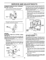
Page 24: ...rtridge plat to expose carburetor choke see AIR FILTER in Main tenance section Choke should be closed If it is not loosen casing clamp screw and move choke cable until choke is completely closed Tighten casing clamp screw securely_ Reassemble air cleaner_ CHOKE CLOSED CASING J CLAMP SCREW CHOKE LEVER FIG 47 TO ADJUST CARBURETOR See Figs 48 and 49 The carburetor has been present at the factory and ...

Page 25: ... to 1200 RPM Release throttle lever ACCELERATION TEST Move throttle control tever from SLOW to FAST position If engine hesitates or dies turn idle mixture screw out counterclockwise 1 8 turn Repeat test and continue to adjust if necessary until engine accel erates smoothly High speed stop is factory adjusted Do not adjust damage may result IMPORTANT NEVER TAMPER WITH THE ENGINE GOVERNOR WHICH IS F...

Page 26: ...r cleaner products in the fuel tank or permanent damage may occur Use fresh fuel next season NOTE Fuel stabilizer is an acceptable alternative in minimizing the formation of fuel gum deposits during stor age Add stabilizer to gasoline in fuel tank or storage container Run engine at least 10 minutes after adding stabilizer to allow the stabilizer to reach the carburetor Do not drain the gas tank an...

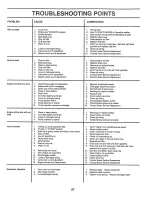
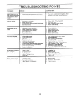
Page 27: ...RECTION 1 Fill fuel tank 2 See TO START ENGINE in Operation section 3 Wait several minutes before attempting to start 4 Replace spark plug 5 Clean replace air filter 6 Replace fuel filter 7 Drain fuel tank and carburetor refill tank with fresh gasoline and rap ace fuel filter 8 Check all wiring 9 Contact Sears Service Department 10 Contact Sears Service Department 1 Clean replace air fitter 2 Rept...

Page 28: ...led 10 Improper bEades used 1 Switch is OFF 2 Bulb s burned out 3 Faulty light switch 4 Loose or damaged wiring 5 Btown fuse 1 Bad battery ceil s 2 Poor cable connect_OnSr 3 Faulty regulator if so equipped 1_ Check wiring switches and connections If not corrected contact Sears Service Department 1 Replace blade Tighten blade bolt 2 Level mower deck_ 3 Clean underside of mower housing 4 Replace bla...

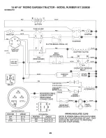
Page 29: ...I I IC Dt t F _ I I B E_ _ AU _ _ PTO DISENGAGED BLACK BLACK t I RED STARTER IGNITION UNIT ELECTRIC CLUTCH RED 5 AMPS DC POS 22 VOLTS AG MtN 5 AMPS DO BATTERY tN LINE NON REMOVABLE CONNECTIONS REMOVABLE CONNECTIONS ALTERNATOR D It IIJE c I t B F 0 UA PTO SWITCH POSITION CIRCUIT J I OFF B E C D ON B A C F WIRING INSULATED CLIPS NOTE IF WIRING INSULATED CLIPS WERE REMOVED FOR SERVICING OF UNIT THEY ...

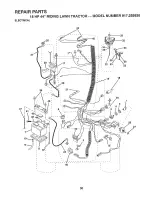
Page 30: ...REPAUR PARTS 18 HP 44 RIDING LAWN TRACTOR MODEL NUMBER 917 255930 ELECTRICAL 23 18 46 30 ...

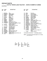
Page 31: ...1 4 20 40 102476X Guard Terminal 14 17190408 Screw Hex Washer Head Thread 41 STD522507 Bolt Hex 1 4 20x3 4 Cutting 1 4 20 x 1 2 42 STD551025 Washer 9 32 x 5 8 x 16 Gauge 15 104445X Switch Interlock 43 STD541025 Nut Hex 1 4 20 16 71031008 Screw HexWashsrHead 44 STD551125 Washer Lock 1 4 10 32 x 1 2 45 110859X Harness Light Socket 17 73951000 Nut Keps 10 32 46 121305X Switch Plunger 18 1063t5X Diode...

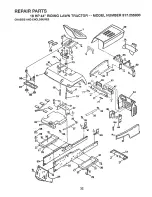
Page 32: ...REPAUR PARTS 18 HP 44 RIDING LAWN TRACTOR MODEL NUMBER 917 255930 CHASSIS AND ENCLOSURES 52 26 _ 26 46 Hr 37 44 79 32 ...

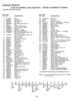
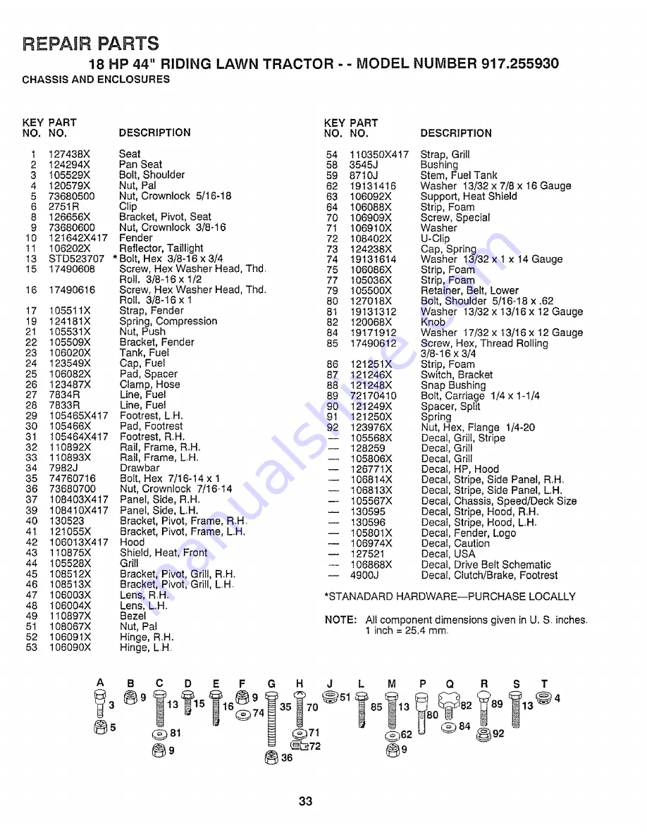
Page 33: ...ill LH 47 106003X Lens R H 48 106004X Lens LH 49 110897X Bezel 51 108067X Nut Pat 52 106091X Hinge R H 53 106090X Hinge L H 54 110350X4 7 58 3545J 59 8710J 62 19131416 63 106092X 64 106088X 70 106909X 71 106910X 72 I08402X 73 124238X 74 19131614 75 106086X 77 105036X 79 105500X 80 127018X 81 19131312 82 120068X 84 19171912 85 17490612 86 121251X 87 121246X 88 21248X 89 72170410 90 121249X 91 12125...

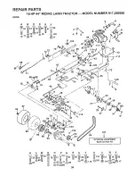
Page 34: ...REPAIR PARTS 18 HP 44 RIDING LAWN TRACTOR MODEL NUMBER 917 255930 DRIVE 86 x 32 130 64 98 92 127 OPTIONAL EQUIPMENT Spark Arrester Kit K L M 62_ N O P O R S T U V W Y 34 ...

Page 35: ...Tube Rear 31 102403X idler Flat 99 65139 Valve Tire 32 19131316 Washer 13 32 x 3 16x 16 Gauge t00 59192 Cap Valve 36 121356X Bracket Clutch inc Key No t06 101 214J Drum Brake 37 207J Washer Hardened 102 STD5414t0 Locknut 10 24 38 12000039 Ktip Ring 103 633A109 Gear Shift Lever Assembly 39 121361X Idler Grooved 104 2228M Key Woodruff 40 STD523715 Bolt Hex 3 8_16x 1 3 4 105 74760720 Bolt Hex 7 16 14...

Page 36: ...REPAIR PARTS 18 HP 44 RiDiNG LAWN TRACTOR MODEL NUMBER 917 255930 STEERING ASSEMBLY 10 10 56 A 83 _ 57 74 21 2 17 36 ...

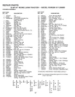
Page 37: ... Dash 45 19171416 Washer 17 32x7 Sx 16Gauge 46 72110622 Bolt Carriage 3 8 16 x 2 3 4 47 121235X Spacer 48 106042X Cover Gate Shift 49 17720408 Screw Hex Washer Head Thread Cutting t 4 20 x 1 2 100710L 74780880 73680800 19172610 120542X 677A451 7190J STD523720 19131413 insert Steering Wheel Bolt Hex 1 2 13x5 Nut Crowntock 1 2 13 Washer 17 32 x 1 5 8 x 10 Bracket Idler Pulley Idler Spring Bolt Hex 3...

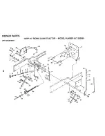
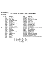
Page 38: ...REPAIR PARTS LIFT ADJUSTMENT 18 HP 44 RIDING LAWN TRACTOR MODEL NUMBER 917 255930 61 J 56 66 18 t_ co 17 64 16 42 16 5_ J 2 6 K K I 40 41 49 23 35_ ...

Page 39: ...t6 Gauge 61 Klip Ring 62 Bracket Lift L H 63 Bolt Shoulder 64 Nut He Flange 1 4 20 65 Link Lift LH 66 Link Lift R H 67 Retainer Spring Button Plunger Lever Lift Rod Detent Plunger Lever STD523710 12563 X 74760624 19171616 9135R 105429X 105413X STD551150 STD541050 105501X STD533707 73680600 674A247 126651X Bolt Hex 3 8 16 x 1 Grip Handle Bolt Hex 3 8 16 x 1 1 2 Washer 17 32 x 1 1 6 x 13 Gauge Sprin...

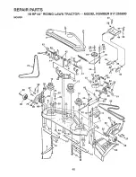
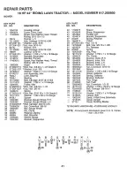
Page 40: ...REPAnR PARTS 18 HP 44 RnDING LAWN TRACTOR MODEL NUiV1BER 917 255930 MOWER 40 73 12 35 51 45 56 48 35 38 17 37 39 4O ...

Page 41: ... 105449X Bracket Gauge Wheel L H_ 34 STD533707 Bolt Carriage 3 8 16 x 3 4 35 73680600 Nut Crownlock 3 8q6 36 105453X Bar Gauge Wheel 37 5565J Pin Clevis 38 4939M Retainer Spring 39 4898H Bolt Shoulder 40 105455X Wheel Gauge 41 105433X Bracket Suspension 42 110237X Spacer 43 105434X Brace Suspension 44 105436X Parallel Link 45 105441X Bracket Suspension 47 3146R Spring Retainer 48 106381X V Belt 49...

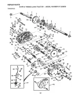
Page 42: ...REPAIR PARTS 18 HP 44 RIDING LAWN TRACTOR MODEL NUMBER 917 255930 TRANSAXLE 80 79 5 20 73 61 59 5 54 53 2 72 71 f98 7 48 41 42 ...

Page 43: ...h Reduction Gear Shaft 87 8739HI 36 4200R 4th Reduction Gear Spacer 88 4924H 37 7395H Thrust Bearing Race 89 19151516 38 121878X Gearcase Gasket 90 110542X 39 122163X Gearcase and Bearings L H 91 19181511 Includes Key Numbers 18 25 49 92 75J 50 2 51 and 52 93 6274H 40 13320400 Pipe Plug 1 2 14 N P T 94 76020412 41 74780526 Bolt Hex 5 16 18 UNC x 1 5 8 95 10040500 42 13170100 Elbow Street 90 96 747...

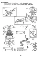
Page 44: ...G LAWN TRACTOR MODEL NUMBER 917 255930 ENGINE BRIGGS STRATTON MODEL NUMBER 422437 TYPE 1266 01 _ _s42 _ _r284A 2_ 25 _ u _ 24 5 1 7 1 354 o _ s2o 10 353 572 9 7 2 5 2 13 337 244 42 41 4O 18 219 35 868 36 33 34 26 j i_19_Krr J 44 ...

Page 45: ...REPAIR PARTS 18 HP 44 RIDING LAWN TRACTOR MODEL NUMBER 917 255930 ENGINE BRIGGS STRATTON MODEL NUMBER 422437 TYPE t266 01 11A 171 549 445 161 201 240 I 5 257 562 45 ...

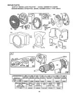
Page 46: ...Thru Bolt Brush Armature Drive End Cap End Cap Ass y Manufacturer DHvs Ass y Assembly I Assembly Assambt_ Assembly Commutator B_kJgs Housing Strattont2v J Length3 5 8 _ 394808 _ I 94003 395538 390837 394860 395537 _erullce Number 5 10 _ i 513 _83 J 876 t 8 96 _t 7 _ rter Drive I _Tt_ _ 1 G a7 Pinion I ROll _ Group Assembly _ Sprln__g_K t I Pin I Brig s Stratton 803 Housing 393825 46 ...

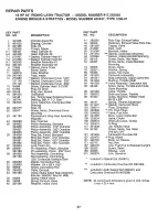
Page 47: ...ssembly Standard Piston Assembly 010 Oversize 117 231338 Piston Assembly 020 Oversize 119 94152 Piston Assembly 030 Oversize Ring Set Piston Standard 121 491539 Ring Set Piston 010 Oversize 127 223472 Ring Set Piston 020 Oversize 161 222752 Ring Set Piston 030 Oversize 171 93715 Lock Piston Pin 187 299146 Pin Assembly Piston Standard 188 93535 Pin Assembly Piston 005 Over 189 90366 Rod Assembly Co...

Page 48: ...ck Shakeproof 869 261463 354 90576 Nut Hex 8 32 870 210940 356 398808 Wire Ground 871 261961 358 394501 Gasket Set 231218 363 19203 Puller Flywheel 877 393537 Optional Accessory 883 272250 383 89838 Wrench Spark Pfug 955 397882 414 223882 Washer 1005 280815 445 394018 Cartddge Air Cleaner 1006 223726 467 212706 Knob Air Cleaner 10t9 491262 474 392595 Stator Alternator Tri Circuit 482 93621 Screw S...

Page 49: ...lilt illll i lll ii i ill i i lll SERVmCE NOTES 49 ...

Page 50: ... ERVmCE NOTES 5O ...

Page 51: ...SUGGESTED GUIDF FOR SIGHTING SLOPES FOR SAFE OPERATION ol SIGHTING ONLY RIDE UP AND DOWN HILL NOT ACROSS HILL SIGHT AN_ HOLD THIS LEVEL WITH SKY LINE _DR TREE 15 MAX ...

Page 52: ...most Retail Stores WHEN ORDERING REPAIR PARTS ALWAYS GIVE THE FOLLOW ING INFORMATION PRODUCT GARDEN TRACTOR MODEL NUMBER 917 255930 ENGINE MODEL NUMBER 422437 TYPE NUMBER 1266 01 PART NUMBER PART DESCRIPTION Your Sears merchandise has added value when you consider Sears has service units nationwide staffed with Sears trained technicians_ profes sional technicians specificaEly trained to insure tha...

Reviews: