background image

Summary of Contents for 917.259564

Page 1: ...s Service and Adjustments Repair Parts CAUTION Read and follow all safety rules and instructions before operating this equipment FOR CONSUMER ASSISTANCE HOT LINE CALL THIS TOLL FREE NUMBER 1 800 659 5917 IIIIIIIIIII 111111111111111111111111111 IIIIIIIII IIIII IIIII IIIIIIIIIIIIIIIII II ...

Page 2: ...ankments_ The mower could suddenly turn over if a wheel is over the edge of a ctiff or ditch or if an edge caves in Do not mow on wet grass Reduced traction could cause sliding Do not tryto stabilize the machine by putting your foot on the ground Do not use grass catcher on steep slopes IlL CHILDREN Tragic accidents can occur if the operator is not alert to the presence of children Chitdren are of...

Page 3: ...ned in effective working order by the operator In the state of California the above is required by taw Section 4442 of the Cafifornia Public Resources Code Other states may have similar laws Federal laws apply on federal lands A spark arrester for the muffler is available through your nearest Sears Authorized Service Center Department See REPAIR PARTS section of this manual i ii u i iii1 1111 H lu...

Page 4: ...reen 18 Cooling Fins Engine 18 Oil Change 17 Oil Level 13 17 OilType 17 Preparation 13 Repair Parts 48 53 Starting 14 Storage 26 F Filters Air 18 Fuel 19 Fuel Type 13 Storage 26 Fuse 24 G Gauge Wheels 8 H Hood Removal installation 24 L Leveling Mower Deck 21 Lubrication Chart 15 M Maintenance Schedule 15 Mower Adjustment Front to Back 21 Adjustment Side to Side 21 Blade Sharpening 16 Blade Replace...

Page 5: ...e installed lets you mulch discharge or bag clippings bagger optional without changing blades For models not equipped as 3 ira1 Convertible mowers See MOWER in the Repair Parts section of this manual RAMP TOPS AND FEET let you load and unload tractor from a pickup truck Use with 2 x 8 or2 x 10 lumber ROLLER for smoother lawn surface 36 inch wide 18 inch diameter water tight drum holds upto 390 Ibs...

Page 6: ...sher 1 2 11 i 11 III M I 1 ii1 1 2 Lock 2 Screws _ _ wo _ 2 Washers t _ 3 16 x 3 4 2 Weld _ _ x16Gauge _ Nuts 10 2 Hex Bolts 1 4 20 x 314 2 Hex Nuts 1 4 20 2 Washers 9 32 x 5 8 x 16 Gauge 2 Lock Was ers 1 4 Steering Wheel Manual Seat Video Cassette _ Mulcher Plate I Steering Boot i Parts Bag i i 111 1111 111 111 i i ul i Parts bag contents not shown full size ii i i ii1 1 1 1 I O_ 2 Washers 318 x ...

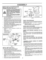
Page 7: ...ering shaft Align mounting holes in extension and lower shafts and install 5 16 hex bott and locknuL Tighten securely IMPORTANT TIGHTEN BOLT AND NUT SECURELY TO I8 22 FT LBS TORQUE Place tabs of steering boot over tab slots in dash and push down to secure INSTALL STEERING WHEEL Position front wheels of the tractor so they are pointing straight forward Slide steering wheel adapter onto steering sha...

Page 8: ...until a comfortable position is reached which allows you to press clutch brake pedal all the way down Get off Seat without moving its adjusted position Raise seat and tighten adjustment bolt securely SEATPAN SHOULDER BOLT FLAT WASHER ADJUSTMENT BOLT LOCKWASHER FIG 3 CHECK TIRE PRESSURE The tires on you rtractor were overinftated at the factory for shipping purpose Correct tire pressure is importan...

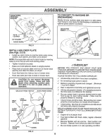
Page 9: ...installation of optional grass catcher accessory DEFLECTOR LATCH HOOKS FIG 6 f CHECKLIST BEFORE YOU OPERATE AND ENJOY YOUR NEW TRACTOR WE WISH TO ASSURE THAT YOU RECEIVE THE BEST PERFORMANCEAND SATISFACTION FROM THIS QUALITY PRODUCT PLEASE REVIEW THE FOLLOWING CHECKLIST All assembly instructions have been completed No remaining loose parts in carton Battery is properly prepared and charged Minimum...

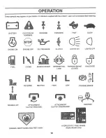
Page 10: ...meaning BATTERY ENGINE ON CAUTION OR SLOW WARNING ENGINE OFF LIGHTS OFF REVERSE FORWARD FAST OIL PRESSURE CLUTCH LIGHTS ON FUEL CHOKE MOWER HEIGHT DIFFERENTIAL PARKING BRAKE LOCK LOCKED UNLOCKED MOWER LIFT REVERSE NEUTRAL ATTACHMENT CLUTCH ENGAGED L HIGH LOW ATTACHMENT CLUTCH DISENGAGED oS PARKING BRAKE IGNITION DANGER KEEP HANDS AND FEET AWAY HYDROSTATIC FREE WHEEL Hydro Models only 10 ...

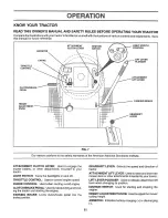
Page 11: ...H LEVER Used to engage the mower blades or other attachments mounted to your tractor LIGHT SWITCH Turns the headlights on and off THRO I I LE CONTROL Used to control engine speed CHOKE CONTROL Used when starting a cotd engine_ Ct UTCHtBRAKE PEDAL Used for declutching and brak ing the tractor and starting the engine PARKING BRAKE Locks clutch brake pedal into the brake position GEARSHIFT LEVER Sele...

Page 12: ...er Start tractor with clutch brake pedal depressed and gearshift lever in neutral N position o Move gearshift and range shift levers to desired posi tion o Slowly release clutch brake pedai to start movement IMPORTANT BRING TRACTOR TO A COMPLETE STOP BEFORE SHiFTiNG OR CHANGING GEARS FAILURE TO DO SO WILL SHORTEN THE USEFUL LIFE OF YOUR TRANSAXLE STOPPING See Fig 8 MOWER BLADES Move attachment clu...

Page 13: ...or to roll stightly as you restart movement 13 CHECK ENGINE OIL LEVEL See Fig 15 The engine inyour tractor has been shipped fromthe factory already filled with summer weight oil Check engine oil with tractor on level ground Remove oil fill cap dipstick and wipe clean reinsert the dipstick and screw cap tight wait for a few seconds remove and read oil level If necessary add oil until FULL mark on d...

Page 14: ...e to reduce load and possible fire hazard from dried clip pings Make fh st cut relatively high the second to the desired height Do not mow grass when it is weL Wet grass will plug mewer and leave undesirable clumps Allow grass to dry before mowing Always operate engine at full throttle when mowing to assure better mowing performance and proper dis charge of material Regulate ground speed by select...

Page 15: ...t axle pivot bolt to 3 5 h 4bs maximum Do not overlighten GENERAL RECOMMENDATIONS The warranty on this tractor does not cover items that have been subjected to operator abuse or negligence To receive full value from the warranty operator must maintain tractor as instructed in this manual Some adjustments will need to be made periodically to properly maintain your tractor All adjustments in the Ser...

Page 16: ...iling edge up towards deck as shown Reassemble hex bolt lock washer and flat washer in exact order as shown Tighten bolt securely 30 35 Ft Lbs torque IMPORTANT BLADE BOLT IS GRADE 8 HEAT TREATED NOTE We do not recommend sharpening blade but if you do be sure the blade is balanced BLADE MANDREL ASSEMBLY TRAILING EDGE LOCK WASHER HEXBOLT GRADE 8 A GRADE 8 HEAT TREATED BOLT CAN BE IDENTIFIED BY SIX L...

Page 17: ...CT SPECIFICATIONS on page 3 of this manual Use gauge on oil fill cap dipstick forchecking level Be sure dipstick cap is tightened securely for accurate reading Keep oil at FULL line on dipstick AIR SCREEN i_ n _ t r _ i t _ _ i _ _DRAIN PLUG ENGINE LUBRICATION Only use high quality detergent oil rated with API service classification SF SG or SH Setect the oil s SAE viscosity grade according to you...

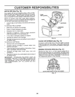
Page 18: ...artridge plate Carefully remove cartridge to prevent debris from entering carburetor o Clean cartridge by tapping gently on flat surface Ifvery dirty or damaged replace cartridge Reinstall cartridge plate cover plate knob and precleaner Reinstall air cleaner cover and reattach clips to sides of air cleaner body IMPORTANT PETROLEUM SOLVENTS SUCH AS KEROSENE ARE NOT TO BE USED TO CLEAN THE CARTRIDGE...

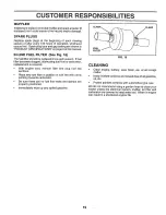
Page 19: ...el flow to carburetor replacement is required o With engine coo remove filter and plug fuel line sections Place new fuel filter in position in fuel line with arrow pointing towards carburetor o Be sure there are no fuel line leaks and damps are properly positioned Immediately wipe up any spilled gasoline FUEL FILTER CLEANING CLAMP FIG 18 Clean engine battery seat finish etc of all foreign matter o...

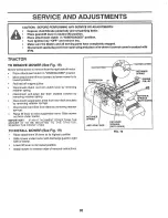
Page 20: ...r mower to its lowest position o Roi belt off engine pulley Disconnect clutch rod from clutch lever by removing retainer spring o Disconnect anti sway bar from chassis bracket by removing retainer spring o Disconnect suspension arms from rear deck brackets by removing retainer springs Disconnect front links from deck by removing retainer springs Raise lift lever to raise suspension arms Slide mowe...

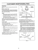
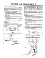
Page 21: ... IMPORTANT DECK MUST BE LEVEL SIDE TO SIDEo IF THE FOLLOWING FRONT TO BACK ADJUSTMENT IS NECESSARY BE SURE TO ADJUST BOTH FRONT LINKS EQUALLY SO MOWER WILL STAY LEVEL SIDE TO SIDE To obtain the best cutting results the mower housing should be adjusted so that the front is approximately 8 to 1 2 lower than the rear when the mower is in its highest position Check adjustment on right side of tractor ...

Page 22: ...easure distance between brake operating arm and nut A on brake rod If distance is other than 1 1 2 loosen jam nut and turn nut A until distance becomes 1 1 2 L Retighten jam nut against nut A Road test tractor for proper stopping distance as stated above Readjust if necessary tf stopping distance is stilJ greater than six 6 feet in highest gear further maintenance is necessary Contact your nearest...

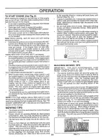
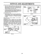
Page 23: ...ooves in rear wheel hub and axle Insert square key Replace washers and snap retaining ring securely in axle groove o Replace axle cover NO fE To seal tire punctures and prevent flat tires due to slow leaks tire sealant may be purchased from your local parts dealer Tire sealant also prevents tire dry rot and corrosion WASHERS RETAINING RING AXLECOVER t SQUARE KEY REAR WHEELONLY FIG 29 TO START ENGI...

Page 24: ...e loosening cable If adjustment is necessary proceed as follows With engine not running move choke control located on dash panel to full choke position o Loosen knob and remove cover assembly from air cleaner o Choke should be closed If it is not loosen casing clamp screw and move choke cable until choke is completely closed Tighten casing cfarnp screw se curely Replace air cteane_ cover assembly ...

Page 25: ...om slow to fast position If engine hesitates or dies turn idle mixture screw out counterclockwise l Sturno Repeat test and continue to adjust if necessary until engine accelerates smoothly High speed stop is factory adjusted Do not adjust damage may result IMPORTANT NEVER TAMPER WITH THE ENGINE GOVERNOR WHICH IS FACTORY SET FOR PROPER ENGINE SPEED OVERSPEEDING THE ENGINE ABOVE THE FACTORY HIGH SPE...

Page 26: ...faces FUEL SYSTEM IMPORTANT iT IS IMPORTANT TO PREVENT GUM DEPOSITS FROM FORMING iN ESSENT AL FUEL SYSTEM PARTS SUCH AS CARBURETOR FUEL FILTER FUEL HOSE OR TANK DURING STORAGE ALSO EXPERIENCE INDICATES THAT ALCOHOL BLENDED FUELS CALLED GASOHOL OR USING ETHANOL OR METHANOL CAN ATTRACT MOISTURE WHICH LEADS TO SEPARATION AND FORMATION OF ACIDS DURING STORAGE ACIDIC GAS CAN DAMAGE THE FUEL SYSTEM OF A...

Page 27: ...ank 2 See TO START ENGINE fn Operation section 3 Wait several minutes before attempting to start 4 Replace spark plug 5 C_eanireplace air filler 6 Replace fuel filter 7 Drain fuel tank and carburetor refill lank with fresh gasoiine and replace fue_ litter 8 Check eli wiring 9 See To Adjust Carburetor in Service Adjustments secfiOnr f 0o Contact an authorized service center department 1_ Clean repl...

Page 28: ...witch is OFF 2 Bulb s burned out 3 Faulty tight switch 4 Loose or damaged wiring 5 Brown fuse 1 Bad battery cell s 2 Poor cabIe connections 3 Faulty regulator if so equipped 4 Faulty alternator l Engine thrott e control not set at SLOW position for 30 seconds before stopping engine CORRECTION 1 Checkwiring switches and connections If not corrected contact an authorized service center department i ...

Page 29: ...TTERY BUT HAVE THEIR OWN ELECTRICAL SOURCE BECAUSE OF THIS THE BRIGHTNESS OF THE LIGHTS WILL CHANGE WITH ENGINE SPEED AT IDLE THE LIGHTS WILL DIM AS THE ENGINE IS SPEEDED UP THE LIGHTS 30 VOLTS AC 3600 RPM REGULATOR DISCONNECTED BROWN HEADLIGHTS 0 _ NON REMOVABLE REMOVABLE CONNECTIONS CONNECTIONS WILt BECOME THEIR BRIGHTEST WIRING INSULATED CLIPS NOTE IF WIRING INSULATED CLIPS WERE REMOVED FOR SER...

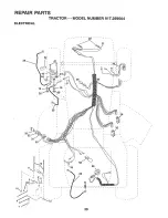
Page 30: ...REPABR PARTS TRACTOR MODEL NUMBER 917 259564 ELECTRICAL t9 20 33 25 x 3O ...

Page 31: ...x 16 Gauge Washer Lock 1 4 Nut Hex 1 4 20 Tube Tray Battery Clamp Hose Bolt Btr Front 1 4 20 x 7 1 2 Holddown Battery Front Mount Nut Push Nylon Battery Front 1 4 Switch Interlock Push ln Washer Lock 1 4 Nut Hex Jam 1 4 20 Harness Light Socket w 4152J Light Bulb Cable Battery Cable Battery Fuse Cable Ground Switch Seat Switch tgnition 4 Position Nut Ignition Cover Ignition Switch Key Molded Crafts...

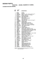
Page 32: ...REPAIR PARTS TRACTOR MODEL NUMBER 917 259564 CHASSIS AND ENCLOSURES 28 58 12 14 14 37 14 32 ...

Page 33: ...le P L Panel Dash RH Screw Thd Roll 3 8 16 x 1 2 Type TT Hood Assembly Bumber Hood Ptate Mtg Battery Fuel Tank Bushing Snap Nylon Fuel Line Washer 13 32 x 13 16 x 12 Gauge Locknut Hex with Insert 3 8 16 UNC Grille W Clips M8 558 Lens Grille Fender Footrest Bracket Fender Support Screw Thdrol 5 16 18 x 1 2 TYT Pivot Bracket Assembly LH Mower Rear Pivot Bracket Assembly RH Mower Rear Nut Lock W Inse...

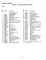
Page 34: ...REPAIR pARTS TRACTOR MODEL NUMBER 917 259564 DRIVE 31 88 87 86 81 84 57 85 13 10 87 21 58 18 113 51 5 18 6t 56 6 32 121 34 ...

Page 35: ... Nylon 85 71208 36 STD551052 Washer 87 19212016 37 STD571810 Roll Pin 88 12000008 38 123574X Pulley Idler Flat 89 154886 39 STD523727 Bolt 90 124346X 40 4470J Spacer Split 395 x 59 96 4497H 41 154777 Keeper Beft Idler Foot Proof 112 19091210 42 19131312 Washer 13 32 x13 16 x12 Gauge 113 127285X 47 127783 Pulley Idler V Groove Plastic 116 72110610 48 154604 Bellcrank Assembly 118 154774 49 123205X ...

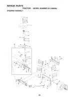
Page 36: ...REPAIR PARTS TRACTOR MODEL NUMBER 917 259564 STEERING ASSEMBLY _ _ 63 _L _ 11 IF _ 25 67 32 28 30 36 ...

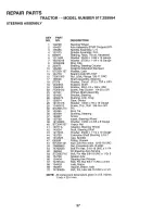
Page 37: ...x 1 1 4 x t6 Gauge Ring_ Ktip Bearing Steering Column Draglink Extended Stamped Washer Lock Bearing Axle STLT GT Nut Lock Flange 5 8 11 UNC Shaft Assembly Steedng Washer Thrust 515 x 750 x _033 Support Shaft Washer Shim 1 4 x 5 8 x _062 Screw Hex Socket 1 4 20 x 5 8 Pittman Shaft Assembiy Bracket Steering Bushing Link Drag Gear Sector Washer 13 32 x 7 8 x 16 Gauge Screw Thd Rol 3 8 16 x 3 4 Pin Ro...

Page 38: ...t Cprsn 2 250 Blk Zi 23 Screw 3 8 16xl 24 Washer 13 32 x 1 x 14 Ga 25 Pan Pnt Seat blk 26 Bracket Pnt Mounting Switch Bushing Snap BIk Nyl 50 Id 72050412 134300 121250X 123976X 153236 STD541431 74780814 19171912 127018X STD551150 DESCRIPTION Bolt Rdhd Sht Nk 1 4_20x1_1 2 Spacer Split 28 X 96 Zinc Spring Cprsn 1 27 Blk Pnt Nut Lock 1 4 Lge Fig Gr 5 Zinc Bolt Shoulder 5 16 18 Unc Nut Lock Hex W Ins ...

Page 39: ...8047 20 156787 22 149516 138311 154515 154516 160978 160979 DESCRIPTION Decal Chassis 42 Decal Mower Drive Schematic Decal Insert Hood Decal Battery Diehard Sears Decal Deck Mower EZ3 Mulching Decal Battery Decal Lift Handle Pad Footrest Lh STLT Pad Footrest Rh STLT Manual Owner s English Manual Owner s Spanish 4 t0 7 11 KEY PART NO NO DESCRIPTION 1 2 3 4 59192 65139 I06222X 59904 5 106732X427 6 2...

Page 40: ...REPAIR ENGINE PARTS TRACTOR MODEL NUMBER 917 259564 78 81 13 10 32 39 40 41 33 16 _x _ t t 29 OPTIONAL EQUIPMENT Spark Arrester 23 35 4O ...

Page 41: ... Right Clamp Tube Double Engine Bolt 5 16 _ 18 UNC X 3 4 W Sems Heat Shield Lt Washer Lock Hvy _Helical 1 4 Order from Engine Manufacturer Bolt Fin Hex 1 4 20 x 3 4 Order from Engine Manufacturer Gasket Muffler Order from Engine Manufacturer Nippte Pipe 4 1 2 Elbow Std 90 Degree 3 8 18 Npt Washer Lock Ext Tooth 3 8 Shield Browning Control Choke Nut Keps 3 8 24 Unf Arrestor Spark Tank Fuel 3 50 Rea...

Page 42: ...RIEPAJRPARTS TRACTOR MODEL NUMBER 917 259564 MOWER LIFT 5 4 6 49 3O 3 26 6 8 I 1 f 1 t l t i 5 32 13 19 20 15 20 15 42 ...

Page 43: ...o Inner with Plunger Shaft Asm Lift Pin Groove E Ring 5 33 62 Washer 21 32 x 1 x 21 G Bearing Nylon Grip Handle Fluted Button Plunger Read Link Lift Lh Fixed Length Link Lift Rh Fixed Length Retainer Spring Link Front Nut Jam Hex 1 2 13 Unc Trunnion Blk Zinc Nut Lock W Wsh 1 2 13 Unc Arm Suspension Rear Retainer Spring Nut Spring Washer 13 32 x 5 8 x 16 Ga Spring 2 1 8 Pin cotter 3 32 x 1 2 Rod Ad...

Page 44: ...REPAnR PARTS TRACTOR MODEL NUMBER 9 7 259564 MOWER DECK 76 75 74 b i_ 40 _ 36 _ _132 34 33 32 31 21 2 27 44 ...

Page 45: ... Gauge 118 Nut Crownlock 3 8 16 UNC 119 Rod Pivot with Nibs 121 Rod Clutch Secondary with Nibs 128 Guard Mandrel L H 129 Retainer 130 Screw Tied Roll 1 4 20 x 5 8 31 Washer Hardened 132 RoIler Assembly Cam Follower _ Bolt Shoulder 10 24 Grade 5 Locknut Bolt Shoulder 5 16 18 UNC Arm Assembly Pad Brake 133943 155046 122052X 140086 t41043 149846 144200 142427 131870 127847 121748X 12000029 128903 127...

Page 46: ...REPAIR PARTS TRACTOR MODEL NUMBER 917 259564 PEERLESS TRANSAXLE MODEL NUMBER 930 057A 68 34 7 35 23 9 31 47 6 8 5 31 13 67 35 77 29 76 15 42A 90 79 43 42 150 46 ...

Page 47: ... 29 780072 Washer Thrust 77 788078A 30 780108 Washer Thrust 31 780001 Washer 79 792144 32 79200 1 O Ring 81 786081 33 788095 Seat Square Cut 34 780105A Bushing Flanged 82 786082 35 780118A Bushing Flanged 83 786123 36 790003 Disk Brake 90 788067B 37 790007 Plate Brake Pad 103 792166 38 799021 Pad Brake Package of 2 104 792167 39 786026 Pin Dowel 150 788093 40 792076A Washer Flat 900 794602 41 7900...

Page 48: ...IGGS STRATTON ENGINE MODEL NUMBER 351777 TYPE NUMBER 1036 A1 523 842 823 823 524 552 8 722 87_ _ 614 0 718 _ 1 _r REQUIRES SPECIAL TOOLS 0 TO INSTALL SEE REPAIR INSTRUCTION MANUAL 978 20 _22 5A 5B 1022 167 171 1023 13A 031 o 1030 166 o 52 122 51 48 ...

Page 49: ...REPAnR PARTS TRACTOR MODEL NUMBER 917 259564 BRIGGS STRATTON ENGINE MODEL NUMBER 351777 TYPE NUMBER 1036 A1 240 o116 243 819 105 137 117A 113 117 I 119 i 387 823 _ _1054A 49 ...

Page 50: ...S TRACTOR MODEL NUMBER 917 259564 BRIGGS STRATTON ENGINE MODEL NUMBER 351777 TYPE NUMBER 1036 A1 467 643 535 445 354_819A 1004 _ 537 265 307 g 351 209A 222 209 23 592 201 9 722 167 116A 116 51 7 358 GASKET SET 50 ...

Page 51: ...REPAIR PARTS TRACTOR MODEL NUMBER 917 259564 BRIGGS STRATTON ENGINE MODEL NUMBER 35 1777 TYPE NUMBER 1036 A1 305 657 _ 78 353 985 _ 354 52O 304 I 1019 LABEL KIT 1054 363 334 668 729A 308 1 o 3 51 ...

Page 52: ... NUMBER 917 259564 BRIGGS STRATrON ENGINE MODEL NUMBER 351777 TYPE NUMBER 1036 A1 3o I 783 513 803 544 310 802 188A 1022 171 1033 VALVE OVERHAUL KIT 113 105 __ 117A 104 117 0 121 CARBURETOR KIT 1036 722 9 BREATHER GASKET SET 52 ...

Page 53: ...size 209A 805453 Ring Set Piston 020 Oversize 2t6 805901 Ring Set Piston _030 Oversize 222 808195 Lock Piston Pin 227 807528 Pin Piston Standard Size 232 805907 Rod Connecting 240 493629 Screw Connecting Rod 243 805964 Valve Exhaust 254 808176 Valve Intake 265 221535 Spring Valve 271 808145 Retainer Valve Spring 277 805018 Retainer Valve 304 808102 Tappet Valve 305 805406 Gear Cam 305A 805902 Mani...

Page 54: ...448 Screw Seres t006 224413 Retainer Fan 527 223167 Clamp Fuel Pipe t014 808105 Shierd Carburetor Air Cleaner 535 272490 Element Foam 1022 806039 Gasket Valve Cover 537 806013 Gasket Air Cleaner 1023 805100 Cover Valve 544 490309 Armature Starter 807665 Cover Valve Used on Cylinder 1 552 805412 Bushing Governor Shaft on Fuel Pump Applications 552A 805413 Bushing Governor Shaft 1024 807546 Pump Ass...

Page 55: ...Z 0 B I t r iil 0 ILl n O I I ILl 0 I t m I t_ n O I 1 Q m Q ILl I ILl t I m Z o 8 _a tro zO Oz t 4 ...

Page 56: ...d on the model plate located under the seat The model number for your engine will be found on the blower housing of the engine Al parts listed herein may be ordered from any Sears Roebuck and Co Service Center Department and most Re tail Stores WHEN ORDERING REPAIR PARTS ALWAYS GIVE THE FOLLOWING INFORMATION PRODUCT TRACTOR MODEL NUMBER 917 259564 ENGINE MODEL NO 351777 1036 A1 PART NUMBER PART DE...

Reviews: