background image

Summary of Contents for 917.271121

Page 1: ...1 Safety Assembly Operation Maintenance Repair Parts CAUTION Read and follow all Safety Rules and Instructions before operating this equip ment Foranswers to your questions about this product Call 1 800 659 5917 Sears Crahsmn Help Une 5 am 5 pro Mon Sat Sears Roebuck and Co Hoffman Estates IL 60179 ...

Page 2: ...ranty service on your Craftsman riding equipment is available at no charge for 30 days from the date of purchase Please contact your nearest service center After 30 days from the date of purchase warranty service is available by taking your Craftsman dding equip ment to your nearest Sears Service Center In home warranty service will still be avail able after 30 days from the date of purchase but a...

Page 3: ...putting your foot on the ground Do not use grass catcher on steep slopes CHILDREN Tragic accidents can occur if the operator is not alert to the presence of children Children are often attracted to the machine and the mowing activity Never assume that children will remain where you last saw them Keep children out of the mowing area and under the watchful care of another responsible adult Be alert ...

Page 4: ... Max not across Remove obstacles such as rocks tree limbs etc Watch for holes ruts or bumps Uneven terrain could overtum the machine Tall grass can hide obstacles Use slow speed Choose a low gear so that you will not have to stop or shift while on the slope Avoid starting or stopping on a slope If tires lose traction disengage the blades and proceed slowly straight down the slope Donottumonslopesu...

Page 5: ...our tractor properly Always observe the SAFETy RULES MAINTENANCE AGREEMENT A Sears Maintenance Agreement is avail able on this product Contact your nearest Sears store for details CUSTOMER RESPONSlBILmES Read and observe the safety rules Follow a regular schedule in maintain ing caring for and using your tractor Follow the instructions under Mainte nance and Storage sections of this owner s manual...

Page 6: ...TS BAG CONTENTS SHOWN FULL SIZE 1 Large Flat Washer O 1 Hex Bolt 3 8 16 x I 1 Lockwasher 3 8 1 Hex Bolt 5 16 18x 1 1 4 1 Locknut 5 16 18 1 Shoulder Bolt 5 16 18 1 Knob 1 Washer 17 32 x 1 3 16 x 12 Gauge 6 ...

Page 7: ...rton Seat Video Cassette Mulcher _ Plate Steermg Whee_ Steering Boot Manual Parts Bag Parts Bag contents not shown full size _ 2 Washers 3 8 2 Shoulder x 718x 14 Ga B lts 2 Ce_nterl ck _ Nuts _ 2 Gauge Wheels Steedng Wheel Adapter U 2 Latch Hook Assemblies Steering 2 Keys Wheel Insert i I I I I i i 1 I Slope Sheet Steering Extension Shaft 7 ...

Page 8: ...OOT washer 3 8 hex bolt and tighten securely Snap steedng wheel insert into center of steering wheel Remove protective materials from trac tor hood and gdll IMPORTANT Check for and remove any staples in skid that may puncture tires where tractor is to roll off skid Slide e_ __sion shaft onto lower steer ing shaft Align mounting holes in exten sion and lower shafts and install 5 16 hex bolt and Ioc...

Page 9: ...able position is reached which allows you to press clutch brake pedal all the way down Get off seat without moving its adjusted position Raise seat and tighten adjustment knob securely Seat Seat Pan Shoulder Bolt Adjustment Knob Rat Washer CHECK TIRE PRESSURE The tires on your tractorwere overinflated at the factory for shippingpurposes Correct tire pressure is important for best cutting performan...

Page 10: ...opening and slide into place as shown Hook front latch into hole on front of mower deck Hook rear latch into hole on back of mower deck A CAUTION Do not remove discharge guard from mower Raise and hold guard when attaching mulcher plate and allow it to rest on plate while in operation TO CONVERT TO BAGGING OR DISCHARGING Simply remove mulcher plate and store in a safe place Your mower is now ready...

Page 11: ...t 6 amps v Seat is adjusted comfortably and tightened securely i All tires are propedy inflated For shipping purposes the tires were ovednflated at the factory V Be sure mower deck is properly leveled side to side front to rear for best cuttin_ results Tires must be properly inflated for leveling Check mower and drive belts Be sure they are routed propedy around pulleys and inside all belt keepers...

Page 12: ...SE FORWARD FAST SLOW OIL PRESSURE LIGHTS ON OVER TEMP t LIGHT FUEL CHOKE MOWER HEIGHT PARKING BRAKE UNLOCKED MOWER LIFT LOCKED R N H L ATTACHMENT REVERSE NEUTRAL HIGH LOW PARKING BRAKE CLUTCH ENGAGED ATTACHMENT KEEP AREA CLEAR SLOPE HAZARDS IGNITION CLUTCH DISENGAGED SEE SAFETY RULES SECTION DANGER KEEP HANDS AND FEET AWAY FREEWHEEL Automatic Modelsonly 12 ...

Page 13: ...ades or other attach ments mounted to your _raq_or LIGHT SWITCH Tums the headlights on and off THROTTLE CHOKE CONTROL Used to control engine speed CLUTCH BRAKE PEDAL Used for declutching and braking the tractor and starting the engine FREEWHEEL CONTROL Disengages transmission for pushing or slowly towing the tractor with the engine off HEIGHT ADJUSTMENT KNOB Used to adjust the mower cutting height...

Page 14: ...ing engine to idle before stopping may cause engine to backfire Turn ignition key to OFP position and remove key Always remove key when leaving tractor to prevent unauthorized use Never use choke to stop engine IMPORTANT Leaving the ignition switch in any position other than OFF will cause the battery to be discharged dead NOTE Under cedain conditions when tractor is standing idle with the engine ...

Page 15: ...al is depressed To restart movement slowly release parking brake and clutch brake pedal Slowly move motion control lever to slowest setting Make all turns slowly TO TRANSPORT When pushing or towing your tractor be sure to disengage transmission by placing freewheel control in freewheeling position Freewheel control is located at the rear drawbar of tractor Raise attachment liftto highest position ...

Page 16: ...E When starting the engine for the first time or if the engine has run out of fuel it will take extra cranking time to move fuel from the tank to the engine Be sure freewheel control is in the transmission engaged position Sit on seat in operating position depress clutchlbrake pedal and set parking brake Place motion control lever in neutral N position Move attachment clutch to DISEN GAGED positio...

Page 17: ... lever in neutral N posi tion slowly disengage clutch brake pedal Slowly move motion control lever for ward after the tractor moves approxi mately five 5 feet slowly move motion control lever to reverse position After the tractor moves approximately five 5 feet return the motion control lever to the neutral N position Repeat this pro cedura with the motion control lever three 3 times Your tractor ...

Page 18: ... interferes with the mulching action The best time to mow your lawn is the early afternoon At this time the grass has dried and the newly cut area will not be exposed to the direct sun For best results adjust the mower cut ting height so that the mower cuts off only the top one third of the grass blades For extremely heavy mulching reduce your width of cut on each pass and mow slowly Certain types...

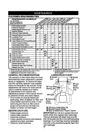
Page 19: ...anty operator must maintain tractor as instructed in this manual Some adjustments will need to be made periodi cally to propedy maintain your tractor All adjustments in the Service and Adjustments section of this manual should be che_ ked at least once each season Once a year you should replace the spark plug clean oPreptace air filter and check blades and belts for wear A new spark plug and clean...

Page 20: ...allow access to blades Remove hex bolt lock washer and flat washer securing blade Install new or resharpened blade with trailing edge TJptowards deck as shown IMPORTANT To ensure proper assembly center hole in blade must align with star on mandrel assembly Reassemble hex bolt Iockwasher and fiat washer in exact order as shown Tighten bolt securely 27 35 R Lbs torque IMPORTANT Blade bolt is Grade 8...

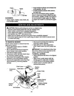
Page 21: ...h API service classification SF SG or SH Select the oil s SAE viscosity grade according to your expected operating tern perature Change the oil after every 50 hours of operation or at least once a year if the tractoris not used for 50 hours in one yeaL Check the crankcase oil level before start ing the engine and after each eight 8 hours of operation tighten oil fill cap dip stick securely each ti...

Page 22: ...aner wing nut cover and tighten knob securely ENGINE OIL FILTER Replace the engine oil filter every season or every other oil change if the tractor is used more than 100 hours in one year Drain oilfrom engine crankcase See TO CHANGE ENGINE OIL in this sec tion of this manual through step remove drain plug Remove oil filter and wipe off filter adapter Apply a thin coating of new engine oil to the r...

Page 23: ...WER Mower will be easier to remove from the right side of tractor Place attachment clutch in DISEN GAGED position Move attachment lift lever forward to lower mower to its lowest position Roll belt off engine pulley Disconnect clutch rod from clutch lever by removing retainer spring Disconnect anti swaybar from chassis bracket by removing retainer spring Disconnect suspension arms from rear deck br...

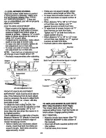
Page 24: ... from trunnion on both front links lightan nut E on both front links an equal number of tums When distance D is 1 8 to 1 2 lower at front than roar tighten nut P against trunnion on both front links Recheck side to side adjustment Mandrel Both Front Links Should be Equal in Length Nut I P Nut G LiftLink Adjustment Nut FRONT TO BACK ADJUSTMENT IMPORTANT Deck must be level side to side If the follow...

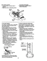
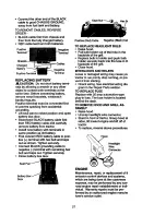
Page 25: ... Readjust if necessary If stopping distance is still greater than six 6 feet in highest gear further maintenance is necessary Contact your nearest authorized ser vice oenter department With Parking Brake _Engaged Nut A Nut Arm Do I _ If further brake adjust rnentis necessary contact your nearest autho rized service center department TO REPLACE MOTION DRIVE BELT Park the tractor on level surface En...

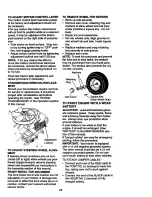
Page 26: ... occurred to affect the front wheel toe in or camber contact your nearest authorized service center TO REMOVE WHEEL FOR REPAIRS Block up axle securely Remove axle cover retaining dng and washers to allow wheel removal rear wheel contains a square key Do not lose Repair tire and reassemble On rear wheels only align grooves in rear wheel hub and axle Insert square key Replace washers and snap retain...

Page 27: ...e terminal with remaining hex bolt and keps nut Tighten securely Close battery box door Hex B_ Positive Red Cable Negative Black Cat TO REPLACE HEADLIGHT BULB Raise hood Pull bulb holder out of the hole in the backside of the grill Replace bulb inholder and push bulb holder securely back into the hole in th backside of the gdll Close hood INTERLOCKS AND RELAYS Loose or damaged widng may cause yol ...

Page 28: ...a limiter cap which allows some adjustment within the limits allowed by the cap Do not attempt to remove the limiter cap The limiter cap cannot be removed without breaking the adjusting needle Be sure you have a clean air filter and the throttle control cable is adjusted propedy see above Start engine and allow to warm for five minutes Make adjustments with engine running and shift motion control ...

Page 29: ...m parts such as carburetor fuel filter fuel hose or tank during storage Also experience indicates that alcohol blended fuels called gasohol or using ethanol or methanol can attract moisture which leads to separation and formation of acids during storage Acidic gas can dam age the fuel system of an engine while in storage Drain the fuel tank Start the engine and let it run until the fuel lines and ...

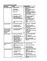
Page 30: ...ower Dirty air filter Low oil level dirtyoil Fillfuel tank See TO START ENGINE _ in Operation section Wait several minutes before attemptingto start Replace spark plug Clean replace air filter Replace fuel filter Drain fuel tank and carburetor refilltank with fresh gasoline and replace fuel filter Check all wiring See To AdjustCarburetor in Service and Adjustments section Contact an authorized ser...

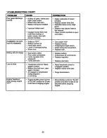
Page 31: ...Wet grass Mower deck not level Low uneven tire air pressure Worn bent or loose blade CORRECTION Clean and regap or change spark plug Replace fuel filter Drain fuel tank and refillwith fresh gasoline Drain fuel tank and carburetor refilltank withfresh gasoline an replace fuel filter Connect and tighten spark plug wire Clean engine air screen fins ClearVreplace muffler Check all widng See ToAdjust C...

Page 32: ...rnator Freewheel control in disen gaged position Motion drive belt worn dam aged or broken Air trapped in transmission dudng shipment or servicing Engine throttlecontrolnot set at SLOW position for 30 sec onds before stoppingengine Clean underside of mower housing Replace mower drive belt Reinstall blades sharp edge down Replace with blades listed in this manual Clean around mandrels to open vent ...

Page 33: ... 85 86 _i 187 30 _ _ _Z_ _ 1 SBAR_ J IGNITION PLUG OPERATOR UNiT GAP 2 PLUGS ON PRESENCE RELAY 2 TfIIN CYL ENGINES BLACK M STATOR _ Rm BRAKE _RO_ IPf Sf_4 I_J_JT IGNt_ON SWITCH tS At4P OC e 3a00 RFt4 _IREGUI _REGULATOR ow ALTERNATOR L OPERATOR PRESENCE RELAY 3 t85 _ i HEADLIGHTS NON REMOVABLE CONNECTIONS REMOVABLE CONNEC_ONS RELAY WIRING INSULATED CUPS NO I_ IF WIRING INSULATED CLIPS WERE REMOVED ...

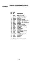
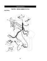
Page 34: ...ELECTRICAL TRACTOR MODEL NUMBER 917 271121 I i 34 ...

Page 35: ...0 onc x 3 4 Case Battery Mech Hinge Switch Interlock N Opn N Opn Washer Lock Nut Hex Jam 1 4 20 UNC Hamese LightSocket Includes4152J Bull Light Cable Battery 6 Gauge Red 11 Cable Battery 6 Gauge Red W 16 Wire Fuse 30Amp Nut Keps Hex 1 4 20 Unc Cable Ground 6 Gauge Black 12 Switch PlungerNormalOp Olico Switch 19nition Nut Igni _n Cover Key Switch Key Ign_don Harness Ignition Bolt Hex Head Fin 1 4 2...

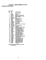
Page 36: ...TRACTOR MODEL NUMBER 917 271121 CHASSIS AND ENCLOSURES 28 58 12 14 11 4 3 3 74 3 51 36 ...

Page 37: ...umper Hood Dash Dash Bolt Carriage 3 8 16 x 1 Panel Dash LH Clip_neerman Gdlle P L Panel Dash R H ScrewThdrol 3 8 16 x 1 2 Hood Assembly Bumper Hood Washer 13 32 x 13 16 x 12 Gauge Nut Gdllew ClipsMS 558 Lens Gdlle Fend Ftrest Pnt STLTN HLD 558 Bracket Fender Support Screw Thdrol 5 16 18 x 1 2 Tyt Pivot BracketAssembly LH PivotBracketAssembly R H Nut Lockw Insert I14 20 UNC Washer 9 32 x 7 8 x 16 ...

Page 38: ...TRACTOR MODEL NUMBER 917 271121 GROUND DRIVE 62 146 27 77 100 H 38 ...

Page 39: ... 104 140156 51 73680600 Nut Crowolock 3 6 16 UNC 105 71070516 52 73680500 Nut Crownlcok 5 16 18 Unc 106 74780520 53 105710X Link Clutch 55 1 _5709X Spring Return Clutch 116 72110610 56 74760620 BoltHex 3 8 16 x 1 1 4 57 140294 V Bait GroundDrive 144 19111016 59 140312 Keeper Cent_Span 145 74490540 61 17490612 SerewT_roll 3 8 16x3 4Ty 146 74490536 IT 147 74490524 62 8883R Cover Pedal 148 159103 63 ...

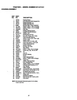
Page 40: ...TRACTOR MODEL NUMBER 917 271121 STEERING ASSEMBLY _M _41 I 62 44 47 67 15 4O ...

Page 41: ...5 6 x 16 Gauge Washer 27 32 x 1 1 4 x 16 Gauge Ring Klip Bearing SteeringColumn DruglinkExtendedStamped Washer Lock BeadngAxle STLT GT Nut Lock Flange 5 8 11 UNC ShaftAssembly steering Washer Thrust 515 x 750 x 033 Support Shaft Washer Shim 114x 5 8 x 062 Screw Hex Socket 1 4 20 x 5 8 Pign_n ShaftAssembly Bracket Steering Bushing Link Drag Gear Sector Washer 13 32 x 7 8 x 16 Gauge Screw Thd Roll 5...

Page 42: ...ENGINE TRACTOR MODEL NUMBER 917 271121 t 8O 33 33 29 _OPTIONAL EQUIPMENT 42 ...

Page 43: ...ne See Breakdown Kohler ModelNo CV16 43513 Muffler Gasket KohlerCV13 CV16 5 Nipple Pipe 3 8 NPT x 3 1 2 Elbow Standard 90 3 8 18 NPT Washer Shield Brn DbrGuard Arrestor Spark Tank Fuel Cap Assembly Fuel Seam Vented Clamp Hose Screw Thdrol 5 16 18 x 3 4 Tyt Une Fuel Plug Oil Drain Order FromEngineManufacturer Bushing Snap Fuel Line Screw FlexWasher Head Thd Ro11 1 4 20 x 3 4 Washer 9 32 x 7 8 x 16 ...

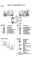
Page 44: ...13 32xl xlOGauge 15 134300 Clip Push In Hinged 16 121250X Nut 17 123976X Spdng Seat 21 153236 Screw Thd Roll 3 8 16xl 22 STO541431 Washer 13 32xl x14Gauge 24 19171912 Pan Seat EmbossQCK Conn KnobSeat 25 127018X DESCRIPTION Bracket SwitchMounting Bushing Snap Bolt Carriage 1 4 20 x 1 1 2 Spacer Split 28 x 88 Spdng Lockout Flange 114Grade 5 Bolt Shoulder 5 16 18 UNC Nut Washer 17 32 x 1 3 16 x 12 Ga...

Page 45: ...riveSchematic Decal V Belt SchamaEc Decal Battery Diehard Decal Battery Dngr Psn Eng Decal FenderAuto Sears Decal Lift Handle Pad FootrestLH S I1 T Pad FootrestRH STLT OwneCsManual Eng sh Owner s Manual SpanPoh WHEELS TIRES 2 _ 5 8 4 10 3 g KEY PART NO NO DESCRIPTION 1 59192 ValveCap Tire 2 65139 Stem Valve 3 106222X Tire Front 4 59904 Tube Front rim Not Provided Sen_lceItem Only 5 106732 X427 Rim...

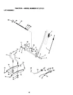
Page 46: ...TRACTOR MODEL NUMBER 917 271121 LIFT ASSEMBLY 29_ 28 27 25 24 23 7 13 49 6 3O 3 26 6 o8 i i 19 13 19 13 15 2O 46 ...

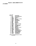
Page 47: ...k Front 16 73350800 Nut He_ Jam 1 2 13 UNC 17 130171 Trunnion 18 73680800 NutCrownlock1 2 13 UNC 19 139868 Arm Suspension Rear 20 163552 RetainerSpring 23 110807X Nut Special 24 19131016 Washer13 32 x 5 8 x 16 Ga 25 2876H Spdug2 1 8 26 76020308 Pin Cotter3 32 1 2 27 126971X Rod AdjUft Zinc 28 73350600 Nut Hex Jam 3 8 16 uric 29 138057 Knob Infi_ 3 8 16 uncBIk Sym 30 1502 33 TrunnionInfinHeight 31 ...

Page 48: ...TRACTOR MODEL NUMBER 917 271121 MOWER DECK 71 17 _ 40 132 83 _ _ 84 58 34 33 31 116 113 111 _14 118 t _ 4 5 6 19_ i 21 J 16 21 28 29 18 _121 22 26 27 48 ...

Page 49: ...sTree 121 143723 36 131494 Pulley Idler Rat 128 153390 37 19131316 Washer 13 32x 13 16x 16 129 19131312 Gauge 130 STD523710 40 STD541437 Nut Crownlock3 8 16 UNC 41 133551 Rod Pivot wi_ N_os 131 STD533710 43 140083 Rod Clutch Secondary with Nibs 132 19132203 44 140088 Guard Mandrel LH 45 STD624003 Retainer 141 6266H 46 137729 Screw Thd Boll 1 4 20 x 5 8 130794 48 133944 Washer Hardened 49 155066 Ro...

Page 50: ...TRACTOR MODEL NUMBER 917 271121 HYDRO GEAR TRANSAXLE MODEL NUMBER 319 0650 58 139 41 28 59 23 19 26 4 35 50 ...

Page 51: ...941 Guide Slot 83 142971 JackshaftAssembly 16 150772 Shaft Motor 85 150806 Jackshaft 19 150773 Bearing Thrust 42x68x16 88 142973 Screw Cap 23 142944 Block CylinderAssembly 89 142974 Washer 7 16 x 1 x 1 2 24 142945 Seal Up 10x25x7 90 142975 SleeveBeadng 25 142946 Actuator Bypass 91 142976 Seal Wiper 26 150774 Center SectionAssemblyKit 92 142977 Spring Block 27 142948 Seal Lip 26 x 42 x 8 93 142978 ...

Page 52: ...TRACTOR MODEL NUMBER 917 271121 KOHLER ENGINE MODEL NUMBER CV16S TYPE NUMBER PS 43513 CYLINDERHEAD VALVE AND BREATHERI 12 11 10 14 _ 15 _ 14 52 ...

Page 53: ...iner breatherreed Reed breather DESCRIPTION 1 2 3 4 5 6 7 8 9 10 11 12 13 14 15 16 17 18 19 2O 21 22 23 24 12032 03 Seal crankshaft Block cylinder Use ShortBlock12 522 18 12 445 02 M 0839025 12 380 17 12 755 49 12 089 18 12 422 08 12 422 09 12 422 10 12 422 11 12 422 12 12 422 13 12 422 07 12 144 19 12 874 07 12 874 08 12 874 09 12 018 02 12 108 07 12 108 08 12 108 09 12 067435 12 067 06 12 380 O1...

Page 54: ...TRACTOR MODEL NUMBER 917 271121 KOHLER ENGINE MODEL NUMBER CV16S TYPE NUMBER PS 43513 IGNITION ELECTRICAL 22 11_ 17 14 AIR INTAKE t 8 BLOWER HOUSING AND BAFFLES i 54 ...

Page 55: ...ector 9 25 154 02 Key 10 SM 0545020 nywheal Connector 4 contact 11 M 0645016 Screw hex cap M5x0 8_5 2 Stator assembly 15 amp 12 12 063 08 Spark Plug 13 12 063 01 Clip cable 2 Screw hex flange M5x0 8xl0 AIR INTAKE FILTRATION 2 Module ignition KEY PART Terminal NO NO Screw hex socket M5xO 8x20 2 1 25 341 03 Screw pan head M4 2x13 2 2 12 096 24 Module speed advance 3 12 083 08 4 12 100 01 5 12 083 05...

Page 56: ...TRACTOR MODEL NUMBER 917 271121 KOHLERENGINE MODEL NUMBERCV16S TYPENUMBERPS 43513 STARTING SYS _EM I g o 3m o O _8m I ENGINE CONTROLS I t0 2 OIL PAN I LUBRICATIONI t 3 _ 0 4 56 ...

Page 57: ...ing upperoHfiHtube Tube oil fill Screw hex flange M5xO Sx20 O Riflg loweroil filltube Screen oil pickup Cove_ oil pickup screen Screw hex flange MSxO 8x16 Valve oil pressurerelief Rug pipe F_er oil Plug sq hd sogd3 8 Pump oilassembly O Ring oilpump cover Cover oil pump Screw hes flange MSxO Sx16 3 sesJ oii P T O end Screw J_ flauge MSx1 2_x45 11 Screw hex flange MSx1 25x45 Pan og ENGINE CONTROLS K...

Page 58: ...58 ...
Page 59: ...GUIDE ONLY RIDE UP AND DOWN HILL NOT ACROSS HILL O1 cO I Operate your Tractor up and down the face of slopes not I greater than 15 never across the face Make turns gradu I ally to prevent tlpplng or loss of control Exerclse extreme ceutlon when changlng dlrectlon on slopes ...

Page 60: ...io de repamci6n a domicilio 1 800 676 5811 For the location of a Sears Parts and Repair Center in your area Call 24 hours a day 7 days a week 1 800 488 1222 For information on purchasing a Sears Maintenance Agreement or to inquire about an existing Agreement Call 9 am 5 pm Monday Saturday 1 800 827 6655 When requesting service or ordering partS always provide th_ following information Product Type...

Reviews: