background image

Summary of Contents for 917.273404

Page 1: ...ously built engines Before you start the engine read and understand this Owner s Manual IMPORTANT Read and follow all Safety Rules and Instructions before operating this equipment For answers to your questions about this product Call 1 800 659 5917 Sears Craftsman Help Line 5 am 5 pm Mon Sat Sears Roebuck and Co Hoffman Estates IL 60179 U S A Visit our Craftsman website www sears com craftsman ...

Page 2: ...ause of operator abuse including but not limited to damage caused by towing objects beyond the capability of the riding equipment impacting objects that bend the frame or crankshaft or over speeding the engine Repairs necessary because of operator negligence including but not limited to elec trical and mechanical damage caused by improper storage failure to use the proper grade and amount of engin...

Page 3: ...es Be sure the area is clear of bystand ers before operating Stop machine if anyone enters the area Never carry passengers Do not mow in reverse unless abso lutely necessary Always look down and behind before and while backing Never direct discharged material toward anyone Avoid discharging material against a wall or obstruction Material may ricochet back toward the operator Stop the blades when c...

Page 4: ...d in the watchful care of a respon sible adult other than the operator Be alert and turn machine off if a child enters the area Before and while backing look behind and down for small children Never carry children even with the blades shut off They may fall off and be seriously injured or interfere with safe machine operation Children who have been given rides in the past may suddenly appear in th...

Page 5: ...r wear gloves and use extra caution when servicing them Check brake operation frequently Ad just and service as required Maintain or replace safety and instruc tion labels as necessary Be sure the area is clear of bystand ers before operating Stop machine if anyone enters the area Never carry passengers Do not mow in reverse unless abso lutely necessary Always look down and behind before and while...

Page 6: ...e Other states may have similar laws Federal laws apply on federal lands A spark arrester for the muffler is available through your nearest Sears service center See REPAIR PARTS section of this manual REPAIR PROTECTION AGREEMENTS Congratulations on making a smart pur chase Your new Craftsman product is designed and manufactured for years of dependable operation But like all prod ucts it may requir...

Page 7: ...knut 1 2 20 Steering Wheel 1 Locknut 1 4 28 n I I n Steering Wheel Adapter 1 Large Flat Washer 1 Hex Bolt 1 4 28 x 1 1 4 _ Steering Extension Shaft Seat 1 Washer 1Lf 32x 1 3 16 x 12 Gauge _ 1 Knob For Future Use Keys Slope Sheet Video Cassette 7 ...

Page 8: ...unting holes in ex tension and lower shafts and install 1 4 hex bolt and Iocknut Tighten securely IMPORTANT Tighten bolt and nut se curely to 10 12 ft Ibs torque 2 Place tabs of steering boot over tab slots in dash and push down to secure INSTALL STEERING WHEEL 3 Position front wheels of the tractor so they are pointing straight forward 4 Remove steering wheel adapter from steering wheel and slide...

Page 9: ...brake pedal 3 Place freewheel control in trans mission disengaged position See TO TRANSPORT in the Operation section of this manual 4 Roll tractor forward off skid 5 Remove banding holding deflector shield up against tractor TO DRIVE TRACTOR OFF SKID See Operation section for location and function of controls _f_ WARNING Before starting read un derstand and follow all instructions in the Operation...

Page 10: ...ted See TO ADJUST BRAKE in the Service and Adjustments section of this manual CHECKL IS T Before you operate your new tractor we wish to assure that you receive the best performance and satisfaction from this quality product Please review the following checklist All assembly instructions have been completed No remaining loose parts in carton Battery is properly prepared and charged Minimum 1 hour ...

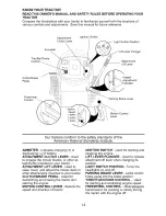
Page 11: ...ld result in serious injury or death The safety alert symbol is used to identify safety inform ation about hazards which can result in death serious injury and or property damage DANGER indicates a hazard which if not avoided will result in death or serious injury WARNING indicates a hazard which if not avoided could result in death or serious injury CAUTION indicates a hazard which if not avoided...

Page 12: ...ging of battery ATTACHMENT CLUTCH LEVER Used to engage the mower blades or other at tachments mounted to your tractor ATTACHMENT LIFT LEVER Used to raise lower and adjust the mower deck or other attachments mounted to your tractor CLUTCH BRAKE PEDAL Used for declutching and braking the tractor and starting the engine MOTION CONTROL LEVER Selects the speed and direction of tractor IGNITION SWITCH U...

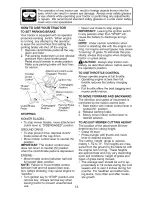
Page 13: ...se engine to backfire Turn ignition key to STOP position and remove key Always remove key when leaving tractor to prevent unauthorized use 13 Never use choke to stop engine IMPORTANT Leaving the ignition switch in any position other than STOP will cause the battery to discharge and go dead NOTE Under certain conditions when tractor is standing idle with the engine run ning hot engine exhaust gases...

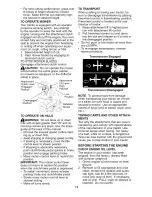
Page 14: ...to neutral N position when the clutch brake pedal is depressed To restart movement slowly release parking brake and clutch brake pedal Slowly move motion control lever to slowest setting Make all turns slowly TO TRANSPORT When pushing or towing your tractor be sure to disengage transmission by placing freewheel control in freewheeling position Freewheel control is located at the rear drawbar of tr...

Page 15: ...trol lever in neutral N position 4 Move attachment clutch to disengaged position 5 Move throttle control to choke position NOTE Before starting read the warm and cold starting procedures below 6 Insert key into ignition and turn key clockwise to start position and release key as soon as engine starts Do not run starter continuously for more than fifteen seconds per minute If the engine does not st...

Page 16: ...y for normal operation MOWING TIPS Mower should be properly leveled for best mowing performance See TO LEVEL MOWER HOUSING in the Service and Adjustments section of this manual The left hand side of mower should be used for trimming Drive so that clippings are discharged onto the area that has already been cut Have the cut area to the right of the trac tor This will result in a more even distri bu...

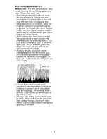
Page 17: ...ps and interferes with the mulching action The best time to mow your lawn is the early afternoon At this time the grass has dried the newly cut area will not be exposed to direct sunlight For best results adjust the mower cutting height so that the mower cuts off only the top one third of the grass blades For extremely heavy grass re duce your width of cut on each pass and mow slowly MAX 1 3 Certa...

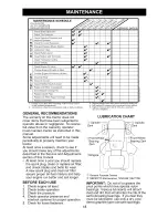
Page 18: ...d in this manual Some adjustments will need to be made periodically to properly maintain your tractor At least once a season check to see if you should make any of the adjustments described in the Service and Adjustments section of this manual At least once a year you should replace the spark plug clean or replace air filter and check blades and belts for wear A new spark plug and clean air filter...

Page 19: ... position to al low access to blades 2 Remove blade bolt lock washer and flat washer securing blade 3 Install new or resharpened blade with trailing edge up towards deck as shown IMPORTANT To ensure proper assembly center hole in blade must align with star on mandrel assembly 4 Reassemble blade bolt lock washer and flat washer in exact order as shown 5 Tighten blade bolt securely 27 35 Ft Lbs torq...

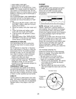
Page 20: ... for the life of the transaxle Should the trans axle ever leak or require servicing contact a Sears or other qualified service center V BELTS Check V belts for deterioration and wear after 100 hours of operation and replace if necessary The belts are not adjustable Replace belts if they begin to slip from wear ENGINE LUBRICATION Only use high quality detergent oil rated with API service classifica...

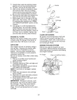
Page 21: ...rvice paper cartridge every 100 hours of operation or every season whichever occurs first Service air cleaner more often under dusty conditions 1 Pull up on air filter cover handle and rotate towards engine 2 Remove cover 3 Carefully remove air filter cartridge and pre cleaner from base 4 Clean base carefully to prevent debris from falling into carburetor NOTE If very dirty or damaged replace cart...

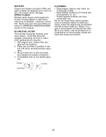
Page 22: ...plug fuel line sections 2 Place new fuel filter in position in fuel line with arrow pointing towards carbu retor 3 Be sure there are no fuel line leaks and clamps are properly positioned 4 Immediately wipe up any spilled gaso line Clamp__ Clamp Fuel Filter CLEANING Clean engine battery seat finish etc of all foreign matter Keep finished surfaces and wheels free of all gasoline oil etc Protect pain...

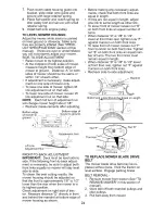
Page 23: ... of bracket 6 Disconnect anti sway bar from chassis bracket by removing retainer spring 7 Disconnect suspension arms from rear deck brackets by removing retainer springs 8 Disconnect front links from deck by removing retainer springs Small Small Retainer Clutch S 9 Raise lift lever to raise suspension arms Slide mower out from under trac tor IMPORTANT If an attachment other than the mower deck is ...

Page 24: ...be sure to adjust both front links equally so mower will stay level side to side To obtain the best cutting results the mower housing should be adjusted so that the front is approximately 1 8 to 1 2 lower than the rear when the mower is in its highest position Check adjustment on right side of trac tor Measure distance D directly in front and behind the mandrel at bottom edge of mower housing as s...

Page 25: ...t A until distance becomes 1 9 16 Retighten jam nut against nut A 4 Engage transmission by placing freewheel control in transmission engaged position Road test tractor for proper stopping distance as stated above Readjust if necessary If stopping distance is still greater than five 5 feet in highest gear further maintenance is neces sary Replace brake pads or contact a Sears or other qualified ser...

Page 26: ...hould be purged after reinstallation and before operating the tractor See PURGE TRANSMISSION in the Operation section of this manual TO ADJUST STEERING WHEEL ALIGN MENT If steering wheel crossbars are not horizontal left to right when wheels are positioned straight forward remove steer ing wheel and reassemble with crossbars horizontal Tighten securely FRONT WHEEL TOE IN CAM BER The front wheel to...

Page 27: ...to prevent sparking from accidental grounding 1 Lift seat pan to raised position 2 Disconnect BLACK battery cable first then RED battery cable and carefully remove battery from tractor 3 Install new battery with terminals in same position as old battery 4 First connect RED battery cable to positive terminal with hex bolt and keps nut as shown Tighten securely Slide terminal cover over terminal 5 C...

Page 28: ...e giving a leaner fuel air mix ture Turning the idle mixture valve out counterclockwise increases the supply of fuel to the engine giving a richer fuel air mixture IMPORTANT Damage to the needle valve and the seat in carburetor may result if screw is turned in too tight PRELIMINARY SETTING 1 Air cleaner assembly must be assem bled to the carburetor when making carburetor adjustments 2 Be sure the ...

Page 29: ...ng in essential fuel system parts such as carburetor fuel hose or tank during storage Also alcohol blended fuels called gasohol or using ethanol or methanol can attract moisture which leads to separation and formation of acids during storage Acidic gas can dam age the fuel system of an engine while in storage Empty the fuel tank by starting the en gine and letting it run until the fuel lines and c...

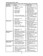
Page 30: ...sh under mower 4 Dirty air filter 5 Low oil level dirty oil 1 Fill fuel tank 2 See TO START ENGINE in Operation section 3 Wait several minutes before attempting to start 4 Replace spark plug 5 Clean replace air filter 6 Replace fuel filter 7 Empty fuel tank and carbure tor refill tank with fresh gas oline and replace fuel filter 8 Check all wiring 9 See To Adjust Carburetor in Service and Adjustme...

Page 31: ...cut uneven Mower blades will not rotate Poor grass discharge 1 Worn bent or loose blade 2 Bent blade mandrel 3 Loose damaged part s 2 3 4 5 Faulty operator safety presence control system Worn bent or loose blade Mower deck not level Buildup of grass leaves and trash under mower Bent blade mandrel Clogged mower deck vent from build up of grass leaves and trash around mandrels 1 Obstruction in clutc...

Page 32: ...lty alternator 1 Freewheel control in disengaged position 2 Motion drive belt worn damaged or broken 3 Air trapped in transmission during shipment or servicing Engine throttle control not set between half and full speed fast position before stopping engine 3 Allow grass to dry before mowing 4 Level mower deck 5 Check tires for proper air pressure 6 Replace sharpen blade Tighten blade bolt 7 Clean ...

Page 33: ... L I_JUE I 14 VOLTS AC MIN 2 _O_ R_ _ _IG_T_ O F F NOTE YOUR TRACTOR IS EQUIPPED WITH A SPECIAL ALTERNATOR SYSTEM THE LIGHTS ARE NOT CONNECTED TO THE BATTERY BUT HAVE THEIR OWN ELECTRICAL SOURCE BECAUSE OF THIS THE BRIGHTNESS OF THE LIGHTS WILL CHANGE WITH ENGINE SPEED AT IDLE THE LIGHTS WILL DIM AS THE ENGINE IS SPEEDED UP THE LIGHTS WILL BECOME THEIR BRIGHTEST BROWN HEADLIGHTS NON REMOVABLE CONN...

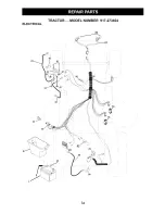
Page 34: ...ELECTRICAL TRACTOR MODEL NUMBER 917 273404 I I I i 42 i i 41 22 J I I i I 26 1 52 29 28 9O J 34 ...

Page 35: ...47 Cable Battery 6 Ga w 16 wire red 26 175158 Fuse 20 AMP 27 73510400 Nut Keps Hex 1 4 20 uric 28 4207J Cable Ground 6 Ga 12 black 29 121305X Switch Plunger Nc Gray 30 175566 Switch Ign 33 140403 Key Ign 40 179720 Harness Ign 41 71110408 Bolt BIk Fin Hex 1 4 20 unc x 112 42 131563 Cover Terminal Red 43 178861 Solenoid 45 121433X Ammeter Rectangular 6 Amp 52 141940 Protection Wire Loop 90 180449 Co...

Page 36: ...TRACTOR MODEL NUMBER 917 273404 CHASSIS AND ENCLOSURES 28 39 278 208 31 2O7 5 209 208 206 209 209 209 209 60 74 209 6O _209 37 209 14 3_ 38_14 208 chassis Laser It stlt 27 36 ...

Page 37: ... 3 8 16 x 1 Panel Dash LH Panel Dash R H Screw Thdrol 3 8 16 x 1 2 Hood Assembly Laser Bumper Extrusion Nut Grille Lens Asm includes s 29 and 212 Lens Fend Ftrest Pnt STLT Bracket Fender Support ScrewThdrol 5 16 18 x 1 2Tyt Bracket Asm Pivot Mower Rear Bracket Pivot Laser Bolt Rdhd Sqnk 3 8 16 uric x 3 4 Dash Lower STLT Nut Crownlock 3 8 16 uric Plate Reinforcement STLT Bracket Swaybar Chassis Bra...

Page 38: ...TRACTOR MODEL NUMBER 917 273404 GROUND DRIVE 30 52 36 35 28 _ I 53 252 25 1 96 78 76 74 75 drive hydro stlt 72 38 ...

Page 39: ...51 STD541437 Nut Crownlock 3 8 16 uric 168 165492 52 STD541431 Nut Crownlock 5 16 18 unc 169 165580 53 105710X Link Clutch 197 169613 55 105709X Spring Return Clutch 198 169845 56 17060620 Screw 3 8 16 x 1 1 4 202 72110614 57 178138 V Belt 212 145212 59 169691 Keeper Center Span 245 178122 61 17120614 Screw 3 8 16 x 875 246 178121 62 8883R Cover Pedal 247 181463 63 175410 Pulley Engine 251 1706051...

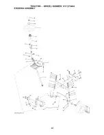
Page 40: ...TRACTOR MODEL NUMBER 917 273404 STEERING ASSEMBLY _39 i i _1 _ 42 I 54 88 J 29 8_ 47 65 28 30 68 67 67 87 13 43 8 40 ...

Page 41: ...pindle Assembly L H Spindle Assembly R H Bearing Race Thrust Hardened Washer 25t32 x 1 5 8 x 16 Ga Ring Klip Draglink Washer Lock Nut Hex Jam Toplock 1 2 20 unf Spacer Bearing Axle Front Nut Hex Flange Lock Shaft Assembly Steering Bushing Link Drag Washer 13t32 x 7 8 x 16 Ga Screw 3 8 16 x 314 Pin Cotter Rod Tie Bushing Steering Screw Insert Steering Wheel Washer 9t16 x 2 3 8 Nut Crownlock 3 8 24 ...

Page 42: ...uffler Exhaust B S Lt Gasket 1 313 Id Tin Plated Tube Drain oil easy Shield Browning Debris Guard Arrestor Spark Tank Fuel 1 25 Fr Cap Asm Fuel Clamp Hose BIk Line Fuel 20 KEY PART NO NO 38 181654 40 124028X 44 17670412 45 17000612 46 19091416 72 183906 78 17060620 81 73510400 DESCRIPTION Plug drain oil easy Bushing Snap Nyl BIk Fuel Line Screw Hexwsh Thdrol 1 4 20 x 3 4 Screw 3 8 16 x 3 4 Washer ...

Page 43: ...nc Spring Seat Cprsn 2 250 BIk Zi Screw 3t8 16 x 1 Washer 13 32 x 1 x 14 Ga Pan Pnt Seat Knob Seat Adj Wingnut Bracket Pnt Mounting Switch KEY PART NO NO DESCRIPTION 13 121248X 14 72050412 15 134300 16 121250X 17 123976X 21 171852 22 STD541431 24 19171912 Bushing Snap BIk Nyl 50 Id Bolt Rdhd Sht Nk 1 4 20 x 1 1 2 Spacer Split 28 x 96 Zinc Spring Cprsn 1 27 BIk Pnt Nut Lock 1 4 Lge Fig Gr 5 Zinc Bo...

Page 44: ... Decal Dash Panel Decal V Belt Schematic Decal Engine Decal Mower Hvy Duty 12 Ga Decal Battery Dngr Psn Eng Decal Disconnect Decal Lift Handle Pad Footrest LH STLT Pad Footrest RH STLT Owner s Manual English Owner s Manual Spanish WHEELS TIRES 2 5 8 7 4 10 wheel 1 KEY PART NO NO 1 59192 2 65139 3 106222X 4 59904 5 106732X624 6 278H 7 9040H 8 106108X624 9 106268X 10 7152J 11 104757X428 144334 DESCR...

Page 45: ...unger 15 173288 Shaft Asm Lift 16 73350800 Pin Groove 17 175689 E Ring 5133 62 18 73800800 Washer 21 32 x 1 x21 Ga 19 139868 Bearing Nylong 20 163552 Grip Handle Fluted 31 169865 Button Plunger Read 32 73540600 Link Asm Lift L H Link Asm Lift R H DESCRIPTION Retainer Spring Link Front Nut Jam Hex 1 2 13 unc Trunnion Nut Lock w Wsh 1 2 13 uric Arm Suspension Mower Retainer Spring Bearing Pvt Lift N...

Page 46: ...TRACTOR MODEL NUMBER 917 273404 MOWER DECK 158 67 185 o L 1051 101 102 _ _ 142 147 103 105 34 5 6 f 19 21 42 D man t path stlt 3 2 16 1 18 13_ 10_ 9_ i i 29 21 28 23 24 25 26 27 46 ...

Page 47: ...Deflector 152 169676 26 110452X Nut Push 158 17720408 27 130968X428 Shield Deflector 159 72140614 28 19111016 Washer 11 32x518x16Ga 184 19131410 29 131491 Rod Hinge 185 188234 30 173984 Screw Thdrol Washer Head 130794 31 187690 Washer Spacer 32 153535 Pulley Mandrel 33 178342 Nut Toplock Flanged 34 72110612 Bolt Carr Sh 3 8 16 x 1 1 2 Gr 5 169583 36 131494 Pulley Idler Flat 40 73900600 Nut Lock 3 ...

Page 48: ...TRACTOR MODEL NUMBER 917 273404 PEERLESS TRANSAXLE MODEL NUMBER LTH2000 115 87 _ _ _ 56 6 31 o _o_7 _ p o _127 k_ 87 200 _ _ lo5 2_ 3_ 832 _ _o L _2o4_ 28 H 185 U 22 25 184 182 _ IO0 48 ...

Page 49: ...5 Washer 627 ID 091W 113 786199 Sleeve Ass y Incl 157 31 780189 Washer 563 ID 062W 114 786200 Sleeve Ass y Incl 87 36 790071 Brake Disk 115 786198 Sleeve Assembly Incl 87 37 790007 Brake Pad Plate 127 784384 Shift Lever Ass y Incl 109 38 799021 Brake Pad 150 788093A Liquid Gasket RTV Silicon 40 792204 Roll Pin 25 157 788102 Oil Seal 9 16 1D 41 790102 Brake Lever 180 730229 BOil Spec 80W90 42 79220...

Page 50: ...R 0299 E1 I 1330 REPAIR MANUAL I 11329 REPLACEMENT ENGINe I 307_ 358 ENGINE GASKET SET 20 6170 868 _ 943 O 1O22 51 _ 691 524 _ 8420 1266 I 1019 LABEL KIT I I 1058 OWNER S MANUAL 11036 EMISSION LABEL I I 750 11 24 15_ J Jl 691 43 _ 741 684 _ 11_ 584_ _ 9_ 1264_ 7_9N 41 12 200 89 1027 50 ...

Page 51: ...IGGS STRATTON ENGINE MODEL NUMBER 31P777 TYPE NUMBER 0299 E1 238 O 1022 1022 216f 232 305A 2651_ 267 _ 559 35 1095 VALVE GASKET SET 617 0 1022 868 525 1119 _ _ _ 643 8o1_ _544_ 803 310_ 579_462 _ 503_ 802 729 697 _ 1070 lO44 t_ 1051_ 51 ...

Page 52: ...947_ 1266 0 118 105A 1127 _ 127A 276A 947A_ NIKKI I B 627t_ 977 CARBURETOR GASKETSET J 51_ 1370 276 I 95 e 121 CARBURETOR OVERHAUL KIT 104 _ 127Q 231 _ 105 _ 137_ ___ 276 634_ _ 106 _ _ 142 6170 117 _ 987 _ 1266 0 1266A O 121ACARBURETOR OVERHAUL KIT 51 _ _ 6170 95A e 634A 104A _ 127AO 987A lO6A _ _o77_ _ 52 ...

Page 53: ...141 495097 Kit Choke Shaft Manual Choke 33 695760 Valve Exhaust 141A 698778 Kit Choke Shaft Nikki 34 695761 Valve intake 142 697140 O Nozzle Carburetor 35 691279 Spring Valve Intake 146 691639 Key Timing 36 691279 Spring Valve Exhaust 187 699331 Line Fuel 37 697352 Guard Flywheel 188 691693 Screw Control Bracket 40 690964 Retainer Valve 192 691986 Adjuster Rocker Arm 43 691968 Slinger Governor Oil...

Page 54: ...29 Nut Starter Cable 1034 690822 Guide Push Rod 584 697112 Cover Breather Passage 1035 693784 Shaft Pump 601 95162 Clamp Hose 1036 695700 Label Emission 614 691620 Pin Cotter 1040 699852 Plate Trim 616 692012 Crank Governor 1044 698139 Screw Flywheel 617 692138 O SeaI O Ring intake Manifold 1051 691265 Ring Retaining 634 690801 O Spring Seal Assembly Manual 1058 275038 Owner s Manual Choke 1059 69...

Page 55: ... DEGREES MAX t Fold this page atong dotted line indicated above 2_Hotd page before you go that its eft edge is vertically para _e_ to a tree trunk or other upright structure 3 Sight across the fold in the direction of h slope you want to measure 4 Compare the angle of the fotd with the stope of the hill ...

Page 56: ...vacuums lawn equipment and electronics call or go on line for the nearest Sears Parts and Repair Center 1 800 488 1222 Anytime day or night U S A only www sears com To purchase a protection agreement U S A or maintenance agreement Canada on a product serviced by Sears 1 800 827 6655 U S A 1 800 361 6665 Canada Para pedir servicio de reparaci6n a domicilio y para ordenar piezas 1 888 SU HOGAR sM 1 ...

Reviews: